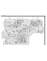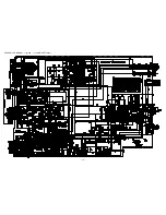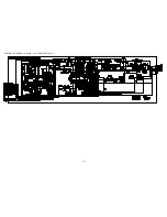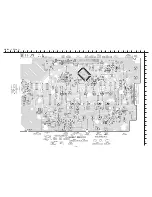
– 27 –
ADJUSTMENT – 1 <TUNER / DECK>
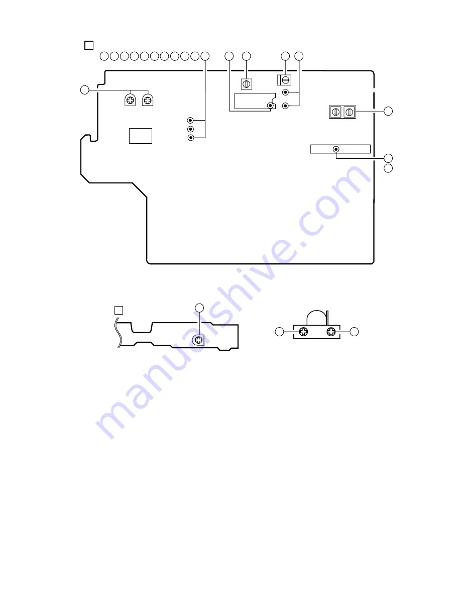
< TUNER SECTION >
1. Clock frequency Check
Settings :
• Test point :
TP2 (CLK)
Method :
Set to AM 1710kHz <LH,U,HA>, AM 1602 kHz
<HS> and check that the test point is 2160kHz
±
45Hz
<LH,U,HA>, 2052kHz
±
45Hz <HS>.
2. AM VT Check
Settings :
• Test point :
TP1 (VT)
Method :
Set to AM 1710kHz <LH,U,HA>, AM 1602 kHz
<HS> and check that the test point is less than 8.5V
<LH,U,HA>, less than 8.0V <HS>. Then set to AM
530kHz <LH,U,HA>, AM 531kHz <HS> and check
that the test point is more than 0.6V.
3. AM Tracking Adjustment
Settings :
• Test point :
TP8 (Lch), TP9 (Rch)
• Adjustment location : L951(1/3)
Method :
Set to AM 1000kHz <LH,U,HA>, AM 999kHz <HS>
and adjust L951(1/3) so that the test point becomes
maximum.
4. AM IF Adjustment
Settings :
• Test point :
TP8 (Lch), TP9 (Rch)
• Adjustment location :
L802 .................................................... 450kHz
5. FM VT Check
Settings :
• Test point :
TP1 (VT)
Method :
Set to FM 87.5MHz and check that the test point is
more than 0.5V. Then set to FM 108.0MHz and check
that the test point is less than 8.0V.
6. FM Tracking Check
Settings :
• Test point :
TP8 (Lch), TP9 (Rch)
Method :
Set to FM 98.0MHz and check that the test point is
less than 9dB
µ
V.
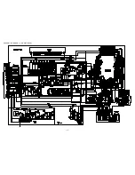
SFR1
DECK–1 P HEAD
DECK–2 R/P/E HEAD
FWD
REV
DECK C.B
D
10
11
11
L951
FFE831
SFR452
IC801
L801
24
TP1(VT)
TP3(DC)
TP9(RCH)
TP8(LCH)
L802
TP2
(CLK)
(3/3) (1/3)
(GND)
SFR451
IC301
TP4(DC)
1
1
MAIN C.B
A
14
15 14 13 12 11 10 9
8
6
4
3
1
7
4
7
3
2
5
Summary of Contents for NSX-AJ24 U
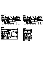
Page 14: ... 14 SCHEMATIC DIAGRAM 1 MAIN 1 2 AMP SECTION ...
Page 15: ... 15 SCHEMATIC DIAGRAM 2 MAIN 2 2 TUNER SECTION ...
Page 17: ... 17 SCHEMATIC DIAGRAM 3 FRONT DECK ...
Page 19: ... 19 SCHEMATIC DIAGRAM 4 PT 24U ONLY ...
Page 21: ... 21 SCHEMATIC DIAGRAM 5 PT EXCEPT 24U ...
Page 23: ... 23 IC BLOCK DIAGRAM ...

