


– 32 –
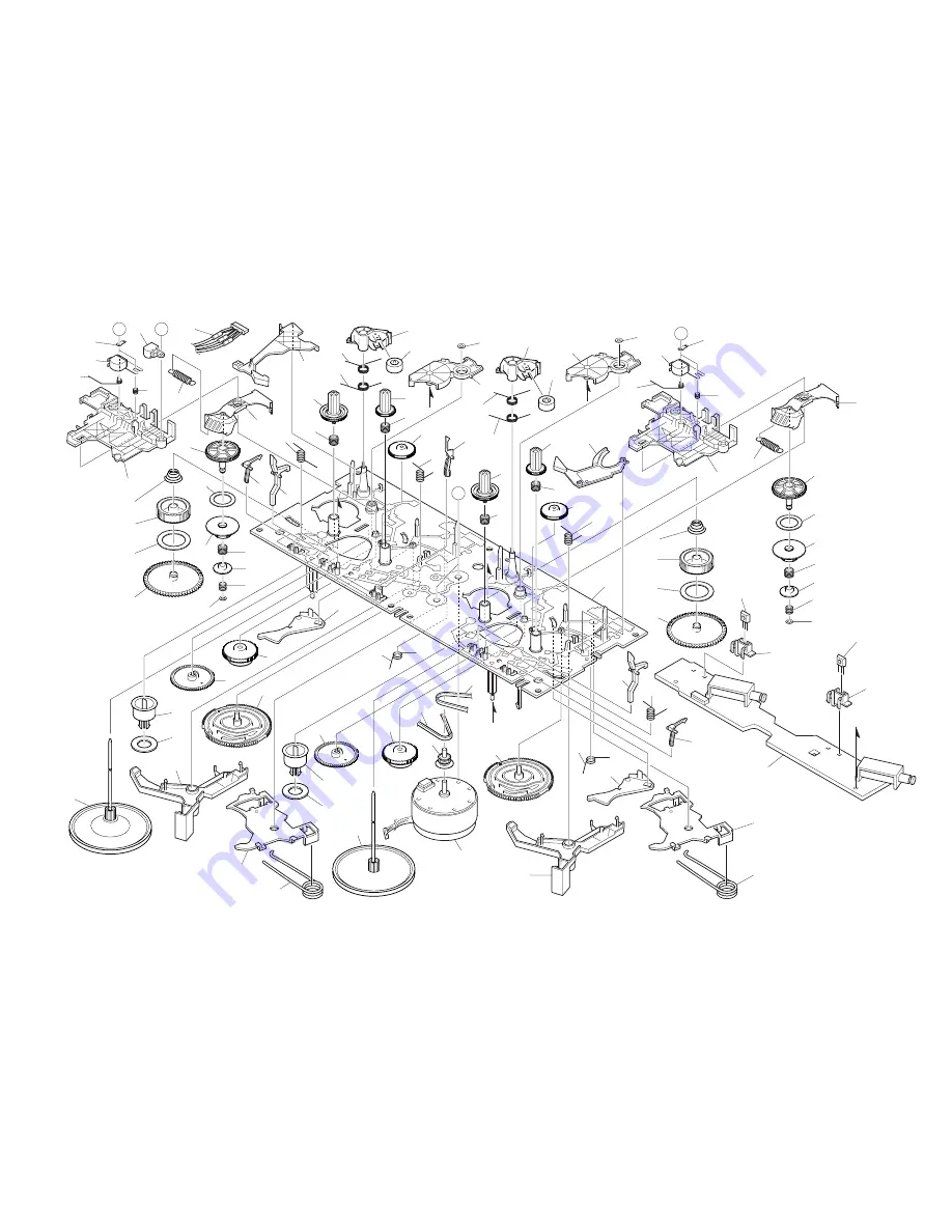
TAPE MECHANISM EXPLODED VIEW 1 / 1
<U>
A
TERMINAL,LB1
A
A
B
TERMINAL,
LB1
1
2
3
4
5
5
6
6
7
8
9
9
10
11
10
11
12
12
13
13
14
14
15
15
16
16
18
18
19
19
20
20
21
21
30
22
23
24
25
26
27
28
22
23
24
25
26
27
28
29
31
32
33
34
35
36
37
37
38
38
39
39
40
41
42
43
44
51
52
45
46
47
48
49
50
53
54
54
17
55
30
35
29
31
32
33
52
51
44
45
43
42
IC, EW732
IC, EW732
b
a
a
b
c
c
40
41
46
47
48
49
PWB
Summary of Contents for NSX-AJ700
Page 12: ... 12 SCHEMATIC DIAGRAM _ 1 MAIN 1 2 AMP SECTION ...
Page 13: ... 13 SCHEMATIC DIAGRAM _ 2 MAIN 2 2 TUNER SECTION ...
Page 14: ... 14 SCHEMATIC DIAGRAM _ 3 PT U ...
Page 17: ... 17 SCHEMATIC DIAGRAM _ 4 U FRONT M OP PANEL S OP PANEL MOTOR BOX SW DECK ...
Page 18: ... 18 SCHEMATIC DIAGRAM _ 5 LH FRONT M OP PANEL S OP PANEL MOTOR BOX SW DECK ...
Page 20: ... 20 SCHEMATIC DIAGRAM _ 6 PT LH ...
Page 23: ... 23 FL BJ815GNK GRID ASSIGNMENT AND ANODE CONNECTION GRID ASSIGNMENT ANODE CONNECTION ...
Page 24: ... 24 IC BLOCK DIAGRAM ...


