


-33-
ELECTRICAL ADJUSTMENT -2/7
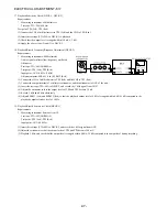
<TUNER Adjustment>
1. VT Adjustment (LW)
Requirements
*
Measuring instrument: Digital multimeter
Test point: VT, GND
Adjustment point: L942
(1) Connect a digital multimeter to VT and GND.
(2) Set the unit function to LW, and adjust the receiving frequency at 144 kHz.
(3) Adjust L942 so that the digital multimeter indicates 1.3
±
0.05 V.
2. VT Check (MW)
Requirements: Same as Item 1
(1) Connect the digital multimeter to VT and GND.
(2) Set the unit function to MW, and adjust the receiving frequency to 1,602 kHz.
(3) Check that the digital multimeter indicates 8.0 V or below.
(4) Adjust the receiving frequency of the unit to 531 kHz.
(5) Check that the digital multimeter indicates 0.5 V or above.
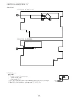
3. VT Adjustment and Check (FM)
Requirements: Same as Item 1.
(1) Connect the digital multimeter to VT and GND.
(2) Set the unit function to FM, and adjust the receiving frequency at 108.0 MHz.
(3) Adjust L907 so that the digital multimeter indicates 7.0
±
0.1 V.
(4) Adjust the receiving frequency of the unit to 87.5 MHz.
(5) Check that the digital multimeter indicates 0.5 V or above.
4. Clock Check (MW)
Requirements
*
Measuring instrument: Frequency counter
Test point: CLOCK, GND
(1) Connect the frequency counter to CLOCK and GND.
(2) Set the unit function to MW, and adjust the receiving frequency to 1,602 kHz.
(3) Check that the frequency counter indicates 2,052 kHz
±
45 Hz.
Summary of Contents for NSX-R17
Page 25: ... 25 SCHEMATIC DIAGRAM 3 5 HP SECTION TO MAIN C B 1 2 AMP SECTION WH101 ...
Page 30: ... 30 SCHEMATIC DIAGRAM 5 5 PT SECTION TO MAIN C B 1 2 AMP SECTION WH001 ...
Page 40: ... 40 FL DISPLAY 1 1 HUA 13SS09T GRID ASSIGNMENT ANODE CONNECTION PINCONNECTION ...
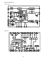
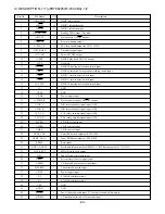
Page 41: ... 41 IC BLOCK DIAGRAM 1 2 IC LC72131D N IC BD3881FV ...
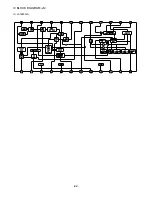
Page 42: ... 42 IC BLOCK DIAGRAM 2 2 IC LA1845N A ...
Page 53: ...2 11 IKENOHATA 1 CHOME TAITO KU TOKYO 110 8710 JAPAN TEL 03 3827 3111 0251431 ...