– 15 –
Drive Adjustment :
2-3. Using the volume keys on the jig remote controller, adjust the figure of 4. G DRIVE to more than 200 until the screen becomes a
greenish color.
2-4. Reduce the figure to the point where the greenish color disappears.
2-5. Using the volume keys on the jig remote controller, adjust the figure of 5. B DRIVE to more than 200 until the screen becomes
bluish color.
2-6. Reduce the figure to the point where the bluish color disappears.
2-7. Repeat the above process of 2-1 to 2-6 for several times to adjust the screen whiter.
Focus Adjustment:
Input signal : Dot pattern
Adjustment point : SFR located at upper part of FBT (T601)
Measuring instrument : Pattern generator / Leader : LCG-404
• Adjust SFR which is located at upper part of FBT (T601) in order to get the best focus point for the dot.
3. Screen Adjustment:
Input signal : No signal (No raster)
Adjustment point : SFR located at lower part of FTB (T601)
Measuring instrument : Pattern generator / Leader : LCG-404
1.
Enter to the “Adjustment Menu Screen” by using the jig remote controller.
2.
Press “0” key of the 10 numeric channel keypad to get a horizontal single line screen.
(Fig. 2-2)
3.
Adjust SFR located at the lower part of FBT (T601) until the horizotal line starts to be
slightly brightened.
4.
Repeat the process of Step 2. and return to the “Adjustment Menu Screen”.
3-1. SUB BRIGHT Sub-brightness Adjustment / Adjustment Menu Screen :
PAGE 3-2 (Make sure of the order)
Input signal : Color bar (Stair step)
Measuring insrument : Pattern generator / Leader : LCG-404
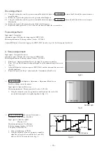
1. Using the volume keys on the jig remote controller, adjust the scale of the
second last from right to be slightly brightened. (Fig. 3-1)
3-2. SUB CONTRAST Sub-contrast Adjustment /
Adjustment Menu Screen : PAGE 3-1
Input signal : Color bar (QIW)
Chroma / Off
Measuring instrument : Oscilloscope
Pattern generator / Leader : LCG-404
Test point : TP902/NK C.B.
1. Connect oscilloscope to TP902.
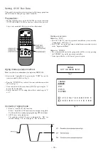
2. Using the volume keys on the jig remote controller,
adjust the voltage between pedestal level and 100%
white to 80V
±
2.0V as shown in the Fig. 3-2
Fig.2-2
PAGE 3
2 SUB BRIGHT
35
2nd from right
Fig.3-1
75%white
100%white
80V+2.0V
Pedestal level
Fig. 3-2


