– 9 –
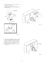
(2) Beam convergence adjustment (4-pole magnet)
Align the R beam with the B beam. The G beam does not
move with this adjustment.
B
G
R
R/B
G
Align the R beam with the B beam
Fig. 1-2
(magenta)
(4) The composition of each magnet is as shown in Fig. 1-4.
In making adjustments, rotate the lock ring clockwise (looking
from the CRT’s back screen) and disengage.
Be careful not to loose the lock ring too much. If the magnet
assembly has become shifted during adjustments, secure it to
the position in Fig. 1-4.
(3) Beam convergence adjustment (6-pole magnet)
With a 4-pole magnet align the G beam with the already aligned
R/B beam.
G
R/B
RGB
(magenta)
(white)
Align the G beam with the R/B beam
Fig. 1-3
CRT
DY
DY lock screw
Purity
4-pole
6-pole
Lock ring
NK C.B
Magnet assembly
Fig 1-4
Magnet assembly
lock screw


