– 19 –
Test Point : IC701 1 pin TV-R
1.Connect oscilloscope to TP701 (IC701 1 pin).
2.Receive TV channel 2.
3.PAGE 5-3
Use the volume keys on the jig remote controller to adjust IC701 1 pin to the
minimum voltage waveform as shown in the Fig. 5-2 (Fig. 5-3)
4. PAGE 5-2
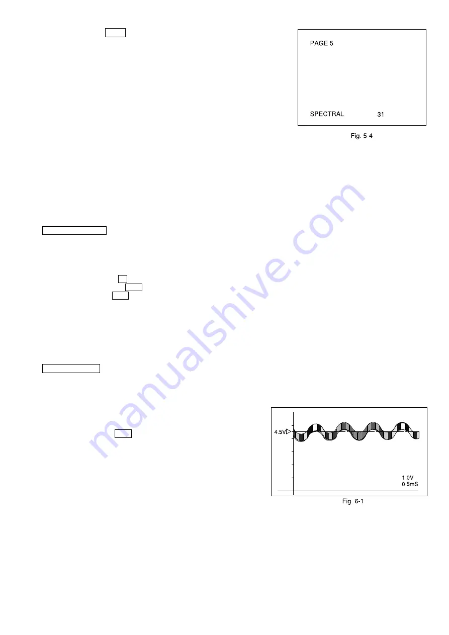
Set internal modulation of TV audio multiple signal generator to 1kHz. Proceed to
adjust as explained in the previous paragraph 3. (Fig. 5-4)
5.Repeat the process of 3 to 4 and set them to the minimum levels.
6. Tuner Adjustment :
Perform the following adjustment in case of replacing any adjustment element during the repair. Proceed
with the following adjustments as well as in the adjustment menu screen. If those adjustments are not
completed on both sides, the required adjustment will not be registered even thought the adjustment has
been processed in the adjustment menu screen.
The components which will be affected due to the repair.
• VCO Coil
• SIF Coil
6-1. VCO ADJUSTMENT VCO(PIF) adjustment / Video Carrier Frequency Free Running Adjustment
Input signal : RF-color bar (Generator)
Input level : 90dB
µ
V (Level may not be exactly the same depends on the receiving condition)
Broadcast CH/fc=45.75MHz
• Simple adjustment method receives normal broadcasting.
Mode : TUNER
Test point : INPUT/TP-102 IF (TU101-11 pin) or receiving condition
OUTPUT/TP-201 AFT (IC301-44 pin)
Adjustment point : L205/ P-IF
Measuring instrument : Oscilloscope
Pattern generator
1. Connect oscilloscope to TP-201.
2. Input specified level of RF signal to TP-102 and adjust L205 until TP-201 voltage becomes 2.8V
±
0.2VDC.
6-2. SIF ADJUSTMENT Stereo IF Modulation Adjustment
Input signal : AM/FM-SG RF OUT/4.5MHz - SIF
MOD OFF
90dB
µ
V
• Simple adjustment method receives normal broadcasting.
Mode : TUNER
Test point : INPUT/TP-202 : IC301-52 pin
OUTPUT/TP-203 : IC301-54 pin
Adjustment point : L201/ S-IF
Measuring instrument : Oscilloscope
AM/FM-Signal generator
1. Connect oscilloscope to TP-203.
2. Input specified signal to TP-202 (or receiving condition) and adjust L201
until TP-203 voltage becomes 4.5V
±
0.2VDC. (Fig. 6-1)


