DISASSEMBLY INSTRUCTIONS
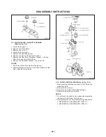
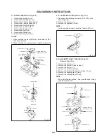
2-11: CYLINDER UNIT (Refer to Fig. 2-11)
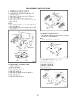
Audio Control Head Base
Audio Control Head
Spring
Audio Control Head
Spring
Audio Control Head
1
1
Fig. 2-10
Deck Chassis
Tension Lever
Spring
Capstan Belt
Position
Marker
2
Fig. 2-12
1
2
2
1
1
1.
2.
3.
Disconnect the following connectors: (CP4101 and CP4102)
on the Head Amp PCB.
Remove the Joint Screw, then remove the Azimuth Spring.
Remove the 2 screws
1
, then remove the Polyslider
Washer and Cylinder Unit from the Main Chassis.
2-13: CENTER PULLEY (Refer to Fig. 2-13)
1. Remove the Polyslider Washer
1
.
2. Remove the Center Pulley.
3. Remove the Polyslider Washer
2
.
4. Remove the Center Pulley Spring.
5. Remove the Idler Arm Ass'y.
6. Remove the 2 Polyslider Washers
3
.
7. Remove the Clutch Gear T Ass'y and Clutch Gear S Ass'y.
Clutch Gear T Ass'y
Center Pulley Spring
Center Pulley
Clutch Gear S Ass'y
Polyslider Washer
1
Fig. 2-13
Polyslider Washer
3
Main Chassis
Azimuth Spring
Joint Screw
1
Cylinder Unit
1
2-12: PLATE BOTTOM (Refer to Fig. 2-12)
1. Remove the Capstan Belt.
2. Remove the 2 screws
1
.
3. Remove the 3 screws
2
.
4. Remove the Mode Switch.
5. Remove the Tension Lever Spring.
6. Remove the Plate Bottom.
NOTE
When installing the Mode Switch, align the timing position.
Polyslider Washer
Fig. 2-11
Mode Switch
Plate Bottom
Polyslider Washer
2
Polyslider Washer
3
Idler Arm Ass'y
B2-4


