DISASSEMBLY INSTRUCTIONS
2.
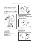
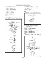
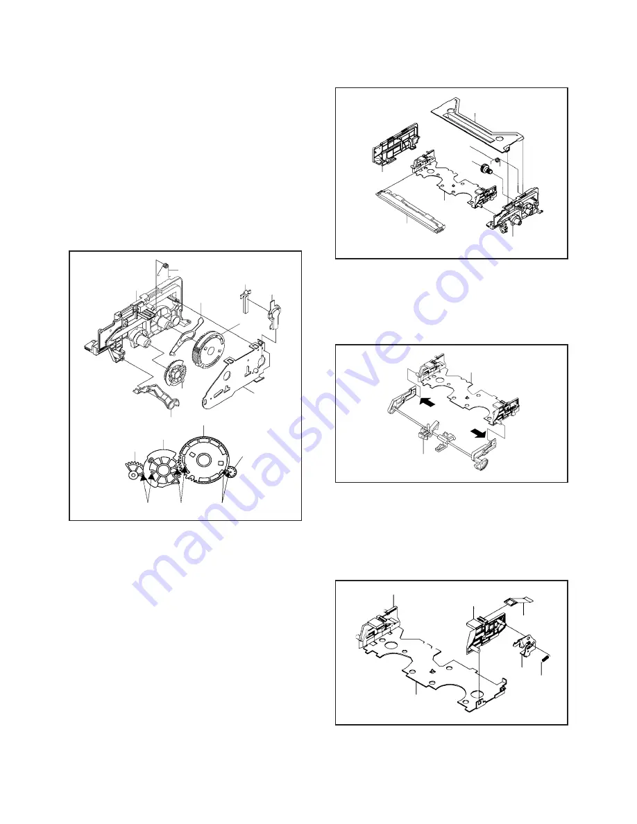
2-1: LINK GEAR (R) / CAM GEAR (Refer to Fig. 2-1)
1.
2.
3.
4.
5.
Unlock the support
1
.
Remove the BOT Sensor Cover and BOT Reflector.
Unlock the 3 supports
2
.
Remove the Side Bracket R2 and Spring Earth.
Remove the Flap Lever, Link Gear (R) , Cam Gear Ass'y
and BOT Lever.
REMOVAL OF DECK PARTS
3
2
2
Side Bracket R1
Cassette
Holder Ass'y
Top Bracket
2
2
Tape Piece
Guide
1
1
Side Bracket L
Fig. 2-2
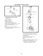
2-3: LINK ASS'Y 2 (Refer to Fig. 2-3)
1. After removing in the direction (A) of Link Ass'y 2, remove
the Link Ass'y 2 in the direction (B).
NOTE
Install the (B) first, then install the (A).
(A)
(B)
Cassette Holder Ass'y
Fig. 2-3
2-4: CASSETTE SIDE R (Refer to Fig. 2-4)
Cassette Holder Ass'y
Locker R
Locker Spring
Pack Spring
Fig. 2-4
1
1
2
1. Unlock the 2 supports
1
.
2. Remove the Cassette Side R.
3. Remove the Pack Spring.
4. Remove the Locker Spring.
5. Unlock support
2
.
6. Remove the Locker R.
Cassette Side L
Cassette Side R
Link Ass'y 2
NOTES
When installing the BOT Lever, insert the BOSS into the
hole of Link Gear (R).
When installing the Link Ass'y 2 and Link Gear (R), align
the timing Marks.
1.
2.
Spring Earth
BOT Lever
BOT Reflector
BOT Sensor
Cover
Cam Gear Ass'y
Side Bracket R1
Side Bracket R2
Cam Gear Ass'y
Flap Lever
Link Gear (R)
Marker
2
2
Fig. 2-1
2-2: TOP BRACKET / TAPE PIECE GUIDE
(Refer to Fig. 2-2)
1. Unlock the 2 supports
1
.
2. Remove the Tape Piece Guide.
3. Unlock the 4 supports
2
.
4. Remove the Top Bracket.
5. Remove the Side Bracket R1 and Side Bracket L.
6. Unlock the support
3
.
7. Remove the Joint Gear.
8. Remove the Bracket R Spring.
Joint Gear
Marker
Marker
1
Link Gear (R)
2
Link Ass'y 2
Bracket R Spring
Joint Gear
B2-1


