DISASSEMBLY INSTRUCTIONS
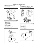
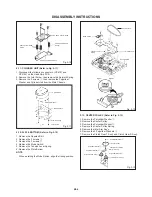
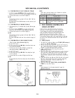
Reel Disk S
Reel Disk T
(A)
(A)
Fig. 2-8
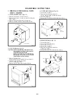
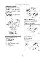
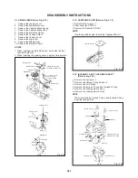
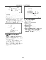
PINCH ROLLER / CASSETTE OPENER
(Refer to Fig. 2-9)
2-9:
Cam Pinch Roller
Cam P5
Arm P5 Ass'y
Cam Pinch Roller
Cam P5
Cassette Opener
Cam Gear
3
Fig. 2-9
Marker
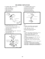
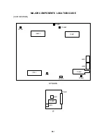
2-10: AUDIO CONTROL HEAD (Refer to Fig. 2-10)
1.
2.
3.
4.
Disconnect the following connector: (CP4106) on the
Head Amp PCB.
Remove the 3 screws
1
.
Remove the 3 Audio Control Head Springs.
Remove the Audio Control Head.
Polyslider Washer
Polyslider Washer
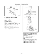
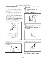
Unlock the support
1
.
Remove the Pinch Roller.
Remove the screw
2
.
Unlock the 2 supports
3
.
Remove the Cassette Opener.
Remove the Spring P5 and Arm P5 Ass'y.
Remove the Cam Gear, Polyslider Washer
4
, Spring
Cam Pinch and Cam Pinch Roller.
Remove the Polyslider Washer
5
and Cam P5.
1.
2.
3.
4.
5.
6.
7.
8.
NOTES
1.
2.
Do not touch the Pinch Roller. (Use gloves.)
When installing the Cam P5, Cam Pinch Roller and
Cam Gear, align the timing marks.
Pinch Roller
2
1
3
Spring P5
Polyslider Washer
5
Cam Gear
Spring Cam Pinch
Polyslider Washer
4
NOTES
1.
2.
Do not touch the head by any means when replacing
the Audio Control Head. (Use gloves.)
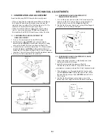
After replacement, confirm the following adjustments.
a. MECHANICAL ADJUSTMENTS: ITEM 2-2
b. MECHANICAL ADJUSTMENTS: ITEM 2-3
B2-3


