

– 17 –
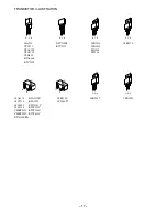
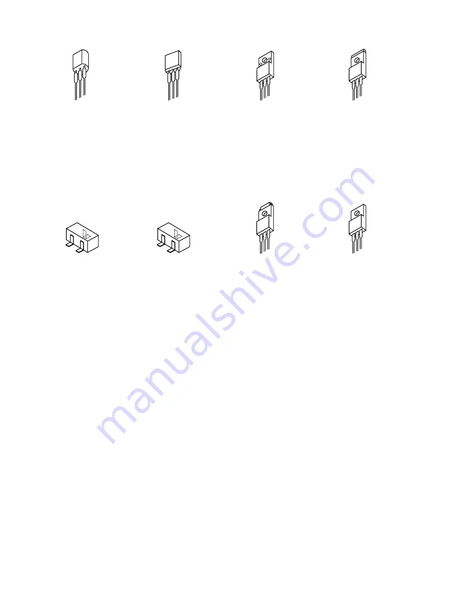
TRANSISTOR ILLUSTRATION
E C B
DTC114ES
KTC3199
E C B
2SA952
CC5551
CSA1585
CSC4115
CSD655
KTA1266
KTC3198
B C E
2SB1370
B
C
E
2SA1235
2SC2714
2SC3052
2SC3326
CMBT5401
CMBT5551
DTA123EKA
G D S
2SK2937
G D S
2SK3053
B C E
2SB1588
2SD2439
FN1016
FP1016
G
D
S
2SK2158
2SJ561-T1
DTA123JK
KTA1298
RT1N141C
RT1P141C
RT1P144C
RT1P441C
Summary of Contents for XH-A1000
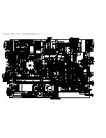
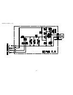
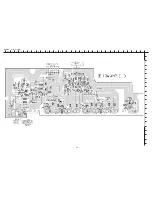
Page 19: ... 19 SCHEMATIC DIAGRAM 1 MAIN 1 4 AMP SECTION CONNECT 1 3 ...
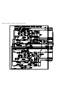
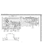
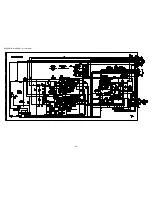
Page 20: ... 20 SCHEMATIC DIAGRAM 2 MAIN 2 4 POWER SUPPLY SECTION ...
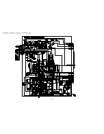
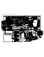
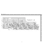
Page 21: ... 21 SCHEMATIC DIAGRAM 3 MAIN 3 4 DECK SECTION ...
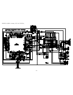
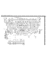
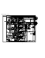
Page 22: ... 22 SCHEMATIC DIAGRAM 4 MAIN 4 4 PRO LOGIC SECTION ...
Page 23: ... 23 SCHEMATIC DIAGRAM 5 FAN ...
Page 25: ... 25 SCHEMATIC DIAGRAM 6 FRONT CONNECT 2 3 DECK DECK MOTOR ...
Page 27: ... 27 SCHEMATIC DIAGRAM 7 OPERATE KEY MIC LED A D ...
Page 29: ... 29 SCHEMATIC DIAGRAM 8 LOW AMP ...
Page 31: ... 31 SCHEMATIC DIAGRAM 9 5CH AMP ...
Page 33: ... 33 SCHEMATIC DIAGRAM 10 VIDEO I O VIDEO JACK VIDEO 3 CONNECT 3 3 ...
Page 34: ... 34 SCHEMATIC DIAGRAM 11 SCART ...
Page 36: ... 36 SCHEMATIC DIAGRAM 12 TUNER ...
Page 38: ... 38 SCHEMATIC DIAGRAM 13 PT ...
Page 40: ... 40 FL BJ733GK GRID ASSIGINMENT ANODE CONNECTION PIN CONNECTION ...
Page 41: ... 41 FL BJ734GK GRID ASSIGINMENT ANODE CONNECTION PIN CONNECTION ...
Page 42: ...IC BLOCK DIAGRAM 42 ...
Page 43: ... 43 ...


