– 8 –
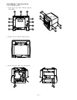
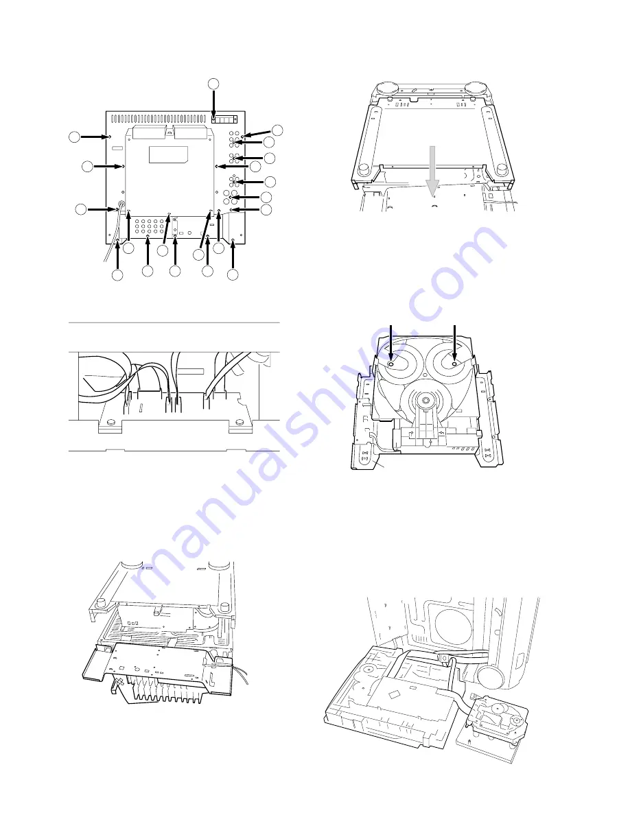
4. Remove the 20 screws (
C
x18,
D
x2) and remove the
CABI, REAR ASSY.
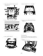
5. Remove the 6 FFCs from the PWB, CONNECT.
6. Remove the PANEL, REAR CD.
7. Remove the CHAS, 3CD together with the AZG-1.
8. Remove the 2 screws and remove the AZG-1 from the
CHAS, 3CD.
The AZG-1 can be repaired while the power is on by using the
jig introduced in the Service Technical Information (SI-98-028).
1. Procedure
Connect the jig as shown below.
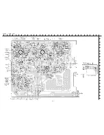
CD service position
C
C
C
C
D
C
C
C
C
C
CABI, REAR
ASSY
C
C
C
D
C
C
C
C
C
C
PWB, CONNECT
PANEL, REAR CD
CHAS, 3CD
CHAS, 3CD
AZG-1
Summary of Contents for XH-A1000
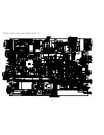
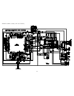
Page 19: ... 19 SCHEMATIC DIAGRAM 1 MAIN 1 4 AMP SECTION CONNECT 1 3 ...
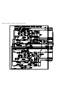
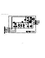
Page 20: ... 20 SCHEMATIC DIAGRAM 2 MAIN 2 4 POWER SUPPLY SECTION ...
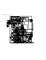
Page 21: ... 21 SCHEMATIC DIAGRAM 3 MAIN 3 4 DECK SECTION ...
Page 22: ... 22 SCHEMATIC DIAGRAM 4 MAIN 4 4 PRO LOGIC SECTION ...
Page 23: ... 23 SCHEMATIC DIAGRAM 5 FAN ...
Page 25: ... 25 SCHEMATIC DIAGRAM 6 FRONT CONNECT 2 3 DECK DECK MOTOR ...
Page 27: ... 27 SCHEMATIC DIAGRAM 7 OPERATE KEY MIC LED A D ...
Page 29: ... 29 SCHEMATIC DIAGRAM 8 LOW AMP ...
Page 31: ... 31 SCHEMATIC DIAGRAM 9 5CH AMP ...
Page 33: ... 33 SCHEMATIC DIAGRAM 10 VIDEO I O VIDEO JACK VIDEO 3 CONNECT 3 3 ...
Page 34: ... 34 SCHEMATIC DIAGRAM 11 SCART ...
Page 36: ... 36 SCHEMATIC DIAGRAM 12 TUNER ...
Page 38: ... 38 SCHEMATIC DIAGRAM 13 PT ...
Page 40: ... 40 FL BJ733GK GRID ASSIGINMENT ANODE CONNECTION PIN CONNECTION ...
Page 41: ... 41 FL BJ734GK GRID ASSIGINMENT ANODE CONNECTION PIN CONNECTION ...
Page 42: ...IC BLOCK DIAGRAM 42 ...
Page 43: ... 43 ...


