


– 50 –
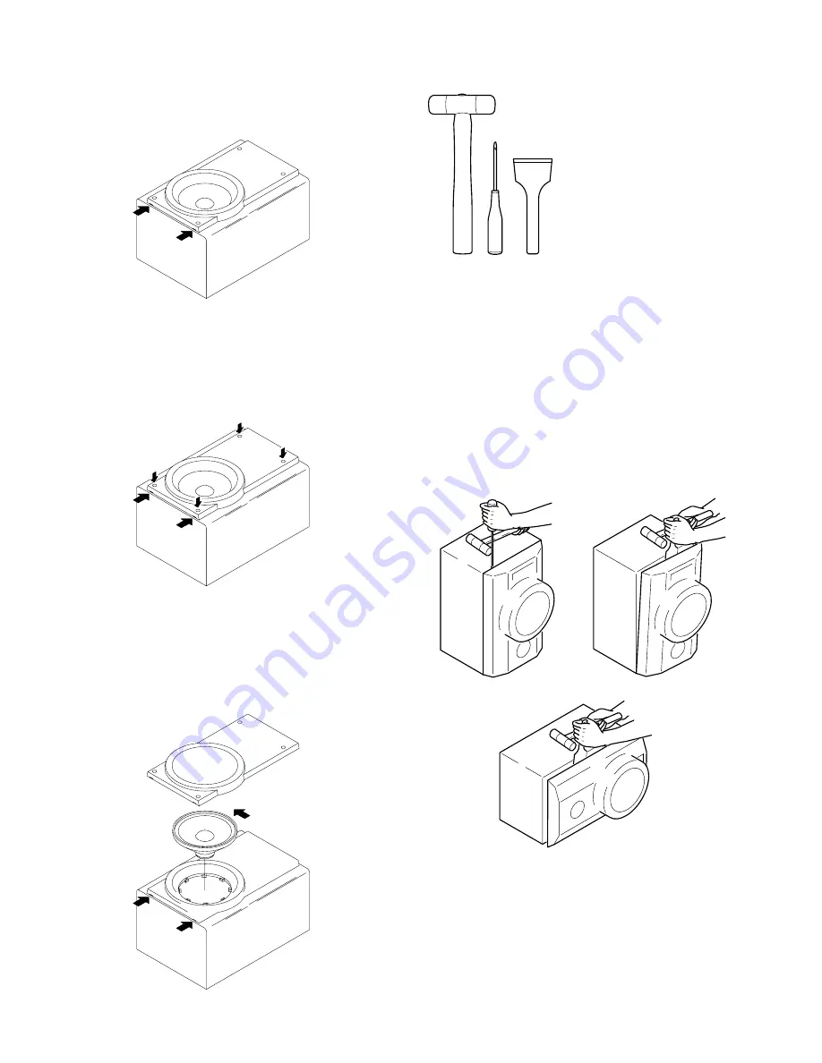
SPEAKER DISASSEMBLY INSTRUCTIONS
Insert a flat-bladed screwdriver into the position indicated by the
arrows and remove the panel. Remove the screws of each speaker
unit and then remove the speaker units.
Type.1
Type.3
Type.2
Type.4
Fig-1
Fig-2
Fig-3
How to Attach the PANEL, FR
Attach the PANEL, FR to the PANEL, SPKR. Tap the four
corners of the PANEL, FR with the plastic hammer to fit the
PANEL, FR into the PANEL, SPKR completely.
1
2
3
Insert a flat-bladed screwdriver into the position indicated by the
arrows and remove the panel. Turn the speaker unit to counter-
clockwise direction while inserting a flat-bladed screwdriver into
one of the hollows around speaker unit, and then remove the speaker
unit. After replacing the speaker unit, install it turning to clockwise
direction until "click" sound comes out.
Remove the grill frame and four pieces of rubber caps by pulling
out with a flat-bladed screwdriver. Remove the screws from hole
where installed rubber caps. Insert a flat-bladed screwdriver into
the position indicated by the arrows and remove the panel. Re-
move the screws of each speaker unit and then remove the speaker
units.
TOOLS
1
Plastic head hammer
2
(
(
) flat head screwdriver
3
Cut chisel
How to Remove the PANEL, FR
1.
Insert the (
(
) flat head screwdriver tip into the gap
between the PANEL, FR and the PANEL, SPKR. Tap the
head of the (
(
) flat head screwdriver with the plastic
hammer head, and create the clearance as shown in Fig-1.
2.
Insert the cut chisel in the clearance, and tap the head of
the cut chisel with plastic hammer as shown in Fig-2, to
remove the PANEL, FR.
3.
Place the speaker horizontally. Tap head of the cut chisel
with plastic hammer as shown in Fig-3, and remove the
PANEL, FR completely.
Summary of Contents for XH-N5
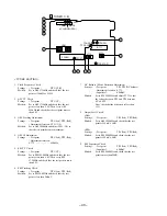
Page 15: ... 15 FL BJ741GK GRID ASSIGNMENT ANODE CONNECTION GRID ASSIGNMENT ...
Page 16: ... 16 ANODE CONNECTION ...
Page 18: ... 18 SCHEMATIC DIAGRAM 1 MAIN 1 2 FUNCTION BBE DSP ECHO CONNECT1 3 ...
Page 19: ... 19 SCHEMATIC DIAGRAM 2 MAIN 2 2 DECK ...
Page 21: ... 21 SCHEMATIC DIAGRAM 3 FRONT DECK DECK MOTOR CONNECT2 3 ...
Page 23: ... 23 SCHEMATIC DIAGRAM 4 OPERATE KEY MIC LED A LED B LED C LED D ...
Page 25: ... 25 SCHEMATIC DIAGRAM 5 AMP AMP C B ...
Page 27: ... 27 SCHEMATIC DIAGRAM 6 VIDEO I O VIDEO JACK VIDEO 3 CONNECT 3 3 ...
Page 28: ... 29 SCHEMATIC DIAGRAM 7 TUNER ...
Page 30: ... 31 SCHEMATIC DIAGRAM 8 PT VOLTAGE SEL SW ...
Page 32: ... 33 IC BLOCK DIAGRAM IC BU4052BCF IC BA7625 ...
Page 33: ... 34 IC BU4094BCF IC BA7762AFS ...
Page 34: ... 35 IC M62445AFP IC SPS 442 1 F ...
Page 35: ... 36 IC BA3880FS IC LC72131D ...
Page 36: ... 37 IC BA3835F IC LA1837NL ...
Page 37: ... 38 IC BU2099FV IC BU9262AFS ...


