-18-
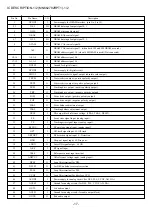
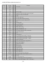
Pin No.
Pin Name
I/O
Description
51
52
53, 54
55
56
57
58
59
60
61
62
63
64
65
66
67
68
69
70
71
72
73
74
75
76
77
78
79
80
AVDD1
FSEL
TMOD1, 2
FLAG
CLVS/IPFLAG
EXT0/ISRDATA
EXT1/ILRCK
EXT2/IBCLK
TX
MCLK
MDATA
MLD
BLKCK
SQCK/BCLK
SUBQ/LRCK
DMUTE/SRDATA
STAT
NRST
SPPOL
PMCK
SMCK
SUBC/SSYNC
SBCK/64FS
NCLDCK
NTEST
X1
X2
DVDD1
DVSS1
I
I
I
O
O
I/O
I/O
I/O
O
I
I
I
O
I/O
O
I/O
O
I
O
O
O
O
I
O
I
I
O
I
I
Power supply for analog circuit (for audio output block).
Noise filter ON/OFF switching input. L: ON. H: OFF.
Terminal mode select input terminal 1, 2. Normal: L.
Flag signal output. (Not connected)
Command selection.
• Spindle servo phase sync signal output. H: CLV. L: Rough servo.
• Interpolation flag signal output.H: Interpolation. (Not connected)
Command selection.
• Extended input/output port 0.
• SRDATA input. (Not connected)
Command selection.
• Extended input/output port 1.
• LRCK input. H: Lch audio data. L: Rch audio data. (Not connected)
Command selection.
• Extended input/output port 2.
• BCLK input. (Not connected)
Digital audio interface output signal.
Microprocessor command clock signal input. (Latches data at raising edge.)
Microprocessor command data signal input.
Microprocessor command load signal input. L: Load.
Sub-code block clock signal. fBLKCK=75 Hz (during normal playback)/SYNC signal
for CDTEXT (DQSY) fDQSY=300 Hz (during normal playback).
Command selection.
• External clock input for sub-code Q register.
• Bit clock output for SRDATA.
Command selection.
• Sub-code Q data output.
• L, R identification signal output. H: Lch audio data. L: Rch audio data.
Command selection.
• Muting input. H: Mute.
• Serial data output.
Status signal. (CRC, RESY, CLVS, NTTSTOP, SQOK, FLAG6, SENSE, NFLOCK,
NTLOCK, BSSEL, SUBQ data, CDTEXT data, anti-shock read-out data)
Reset input. L: Reset.
Spindle motor drive signal output (polarity output).
88.2 KHz clock signal output.
4.2336 MHz clock signal output.
Command selection.
• Sub-code serial output.
• Sector SYNC output. (Not connected)
Command selection.
• Clock input for sub-code serial output.
• 64 FS output. (Not connected)
Sub-code frame clock signal output. (fCLDCK=7.35 KHz) (Not connected)
Test terminal: Normally H.
Crystal oscillator circuit input terminal. f=16.9344 MHz.
Crystal oscillator circuit output terminal. f=16.9344 MHz.
Power supply for digital circuit.
Ground for digital circuit.
IC DESCRIPTION-1/2 (MN662782RPT1)-2/2
Summary of Contents for XP-V420
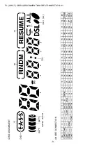
Page 8: ...8 FL AHC 7 GRID ASSIGNMENT ANODE CONNECTION 1 1 GRID ASSIGNMENT ANODE CONNECTION...
Page 9: ...9 SCHEMATIC DIAGRAM 1 1...
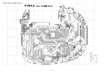
Page 10: ...10 WIRING 1 2 MAIN COMPONENT SIDE...
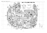
Page 11: ...11 WIRING 2 2 MAIN CONDUCTOR SIDE...
Page 26: ...26 CD MECHANISM EXPLODED VIEW 1 1 DA23LH 6 A C B 3 1 7 4 5 2 8...


