-20-
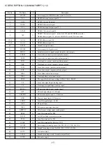
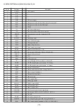
Pin No.
Pin Name
I/O
Description
45
46
47
48
49
50
51
52
53
54
55
56
57
58
59
60
61
62
63
64-79
80
DSL1
MUTE
STANDBY
LCDRDO
P-OFF
DSCHRG
CHRG
BAT-F
BAT-M
BAT-E
2.5V
SWCL
ELON
SPCON
CAR_LED
E-MODE
TEST
M1/NM2
NC
SEG15-0
NC
O
O
O
O
O
O
O
O
O
O
O
O
O
O
O
I
I
I
—
—
—
DSL ON control output of headphones. DSL ON= H.
Audio mute output.
Standby output of headphones. During standby =L. Power on= H.
Wired LCD remote control output. (Not connected)
Power-off output of power supply IC. L= Power off.
Discharge output.
Charge output.
Full indication LED output of battery remaining amount display. L= LED ON. (Not connected)
Medium indication LED output of battery remaining amount display. L= LED ON.
(Not connected)
Empty indication LED output of battery remaining amount display. L= LED ON.
(Not connected)
Not used.
Open/close detection switch input of lid.
EL backlight control output. (Not connected)
Spindle PWM control output.
Outputs to light button LED of CAR-KIT model. H= Lights.
Spindle-loss mode. (H= There is no spindle-loss mode).
L= Enters TEST mode.
Input to select either 10 seconds or 10/40 seconds by AHC-5. H= 10 seconds. L= 10/40
seconds.
Not used.
LCD segment output.
Not used.
IC DESCRIPTION-2/2 (MN101C439-AE)-2/2
Summary of Contents for XP-V420
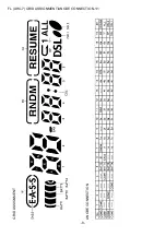
Page 8: ...8 FL AHC 7 GRID ASSIGNMENT ANODE CONNECTION 1 1 GRID ASSIGNMENT ANODE CONNECTION...
Page 9: ...9 SCHEMATIC DIAGRAM 1 1...
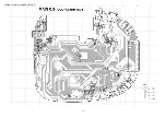
Page 10: ...10 WIRING 1 2 MAIN COMPONENT SIDE...
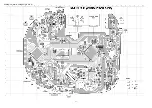
Page 11: ...11 WIRING 2 2 MAIN CONDUCTOR SIDE...
Page 26: ...26 CD MECHANISM EXPLODED VIEW 1 1 DA23LH 6 A C B 3 1 7 4 5 2 8...


