background image

-25-

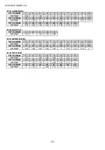
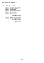
COLOR NAME TABLE

Basic color symbol

Color

Basic color symbol

Color

Basic color symbol

Color

B

Black

C

Cream

D

Orange

G

Green

H

Gray

L

Blue

LT

Transparent Blue

N

Gold

P

Pink

R

Red

S

Silver

ST

Titan Silver

T

Brown

V

Violet

W

White

WT

Transparent White

Y

Yellow

YT

Transparent Yellow

LM

Metallic Blue

LL

Light Blue

GT

Transparent Green

LD

Dark Blue

DT

Transparent Orange

GM

Metallic Green

YM

Metallic Yellow

DM

Metallic Orange

PT

Transparent Pink

LA

Aqua Blue

GL

Light Green

Summary of Contents for XP-V420

Page 1: ...SERVICE MANUAL D A T A BASIC CD MECHANISM DA23LH COMPACT DISC PLAYER XP V420 XP V421 XP V422 XP V423 XP V426C S M Code No 09 013 354 9N1 Y1 S B AEZ1 S AEZ1 S YL1 S DT YT LT YL1 S...

Page 2: ...V420 XP V421 V422 XP V426C V423 Design and specifications are subject to change without notice Design and specifications are subject to change without notice Design and specifications are subject to c...

Page 3: ...those specified herein may result in hazardous radiation exposure ATTENTION L utilisation de commandes r glages ou proc dures autres que ceux sp cifi s peut entra ner une dangereuse exposition aux ra...

Page 4: ...e connection remove solder shown in the right figure Body or clothes electrostatic potential could ruin laser diode in the optical block Be sure ground body and workbench and use care the clothes do n...

Page 5: ...080 CAP 15P C419 87 012 176 080 CAP 15P C420 87 A10 260 080 C CAP U 0 1 16 K B C421 87 A10 260 080 C CAP U 0 1 16 K B C422 87 A10 260 080 C CAP U 0 1 16 K B C451 87 A10 260 080 C CAP U 0 1 16 K B C50...

Page 6: ...SW TACT SKHHAJ S307 87 036 349 010 SW TACT SKHHAJ S308 87 036 349 010 SW TACT SKHHAJ S309 87 036 349 010 SW TACT SKHHAJ VR701 87 A90 462 010 VR RTRY 30KCX2 H RK14J12A0 X401 81 592 641 010 VIB CER 16...

Page 7: ...7 TRANSISTOR ILLUSTRATION 1 1 B E C E1 B1 C2 C1 B2 E2 B C E 2SA1162 2SC2412 2SC2712 CPH3106 CPH3206 DTC114EK DTC114TK DTC123JK RN2411 IMH4A 2SB1132 2SD1664...

Page 8: ...8 FL AHC 7 GRID ASSIGNMENT ANODE CONNECTION 1 1 GRID ASSIGNMENT ANODE CONNECTION...

Page 9: ...9 SCHEMATIC DIAGRAM 1 1...

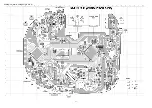
Page 10: ...10 WIRING 1 2 MAIN COMPONENT SIDE...

Page 11: ...11 WIRING 2 2 MAIN CONDUCTOR SIDE...

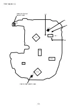
Page 12: ...12 TEST MODE 1 3 S303 OPEN CLOSE SW SHORT LAND IC502 IC501 IC701 IC301 TEST MODE SHORT LAND VC TE FE RF IC401 IC451 IC601 61 7 20...

Page 13: ...and 3 can be verified even if the TOC cannot be read Note 2 By repeatedly pressing the DISPLAY ENTER button all the LCDs light up and the TOC display is repeated Note 3 By repeatedly pressing the DSL...

Page 14: ...ile playing the test disc and confirm the TE waveform is as shown below VOLT DIV 200mV TIME DIV 2ms 6 Confirmation of each servo It is possible to confirm the adjustment value of each servo by repeate...

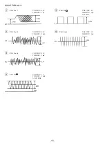
Page 15: ...IV 0 5V TIME DIV 1 S 2 IC501 Pin VOLT DIV 0 2V TIME DIV 50 S 3 IC501 Pin VOLT DIV 0 1V TIME DIV 2mS 4 IC401 Pin VOLT DIV 1V TIME DIV 50mS f 16 93MHz 78 71 5 IC401 Pin VOLT DIV 2V TIME DIV 5 S f 44 1kH...

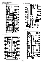
Page 16: ...DIAGRAM 1 1 IC BA6655AFV IC AN8838NSB IC AN8746SA IC TA2120FN power off Ref vol Regulator ST PULSE Switching driver Vref2 Ref vol Vref1 BST Starter Starter Normal Power switch 2 Power switch 1 DET DE...

Page 17: ...e motor drive signal output absolute value output Traverse drive output positive polarity output Traverse drive output negative polarity output Tracking drive output positive polarity output Tracking...

Page 18: ...command clock signal input Latches data at raising edge Microprocessor command data signal input Microprocessor command load signal input L Load Sub code block clock signal fBLKCK 75 Hz during normal...

Page 19: ...t connected Processor mode is not used Connected to VSS VSS Function key input PLAY STOP KEY input AC adapter detection Battery voltage detection Wired remote control input Digital out ON OFF input L...

Page 20: ...output Charge output Full indication LED output of battery remaining amount display L LED ON Not connected Medium indication LED output of battery remaining amount display L LED ON Not connected Empty...

Page 21: ...CD PLAY 0 94 1 85 2 79 2 89 1 43 1 34 PIN S NUMBER 11 12 13 14 15 16 17 18 19 20 CD PLAY 0 0 2 88 0 0 2 86 2 86 0 2 05 0 PIN S NUMBER 21 22 23 24 25 26 27 28 29 30 CD PLAY 0 2 86 2 10 2 89 2 88 2 89 0...

Page 22: ...JU7012F PIN S NUMBER 1 2 3 4 5 CD PLAY 1 43 0 1 43 1 43 2 89 IC451 MSM51V4400D PIN S NUMBER 1 2 3 4 5 6 7 8 9 10 CD PLAY 1 45 1 40 2 72 0 12 0 16 0 49 0 48 0 16 0 50 2 88 PIN S NUMBER 11 12 13 14 15 1...

Page 23: ...23 MECHANICAL EXPLODED VIEW 1 1 a a B D A 10 11 12 13 15 14 8 8 8 LCD DA23LH 5 PWB 7 6 9 18 16 17 19 23 3 4 1 2 C D C D 20 21 22...

Page 24: ...LID CD 420 S EXCEPT 423YL1DTCC 423YL1YTCC 423YL1LTCC 423YL1BDTCC 423YL1BYTCC 423YL1BLTCC 11 8B HCH 067 010 LID CD BDT 11 8B HCH 066 010 LID CD BLT 11 8B HCH 068 010 LID CD BYT 11 8B HCH 062 010 LID CD...

Page 25: ...Blue LT Transparent Blue N Gold P Pink R Red S Silver ST Titan Silver T Brown V Violet W White WT Transparent White Y Yellow YT Transparent Yellow LM Metallic Blue LL Light Blue GT Transparent Green L...

Page 26: ...26 CD MECHANISM EXPLODED VIEW 1 1 DA23LH 6 A C B 3 1 7 4 5 2 8...

Page 27: ...CKUP LASER ASSY 2 S0 M10 A13 500 MOTOR ASSY SPDL LH 3 S0 M10 A10 900 MOTOR SLED ASSY 4 S0 551 A00 900 SPINDLE ASSY SCREW 5 S2 451 A18 100 HOLDER GEAR 6 S2 511 A23 200 GEAR MIDDLE 7 S2 511 A23 400 GEAR...

Page 28: ...T 422AEZ1SC 421AEZ1SC 422AEZ1BSC 420Y1SC 1 8B HCH 925 110 IB Y EGF C 420 420Y1SC 1 8B HCH 927 110 IB Y PHNCZ C 420 420Y1SC 1 8B HCH 926 110 IB Y SID C 420 420Y1SC 2 87 B30 283 110 AC ADAPTOR AC D603EN...

Page 29: ...2 11 IKENOHATA 1 CHOME TAITO KU TOKYO 110 8710 JAPAN TEL 03 3827 3111 H251701 Printed in Singapore...

Reviews: