<CD SECTION>
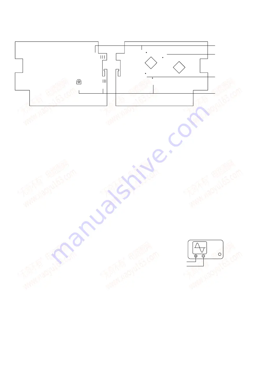
CD C.B (PART SIDE) CD C.B (PATTERN SIDE)
RF
Vref
TE
FE
SFR501
Vref
FE
① ②③ ④
②③
④
①
Perform the adjustments after the main unit enters the test mode.
Place the CD mechanism on level ground.
Equipment and tools required
Measuring equipment
Digital multi-meter
Jitter meter (KIKUSUI 6235)
Test disc: TCD-782
ATD-001
1.FOCUS OFFSET ADJUSTMENT
1) Connect a digital multimeter to the FE and Vref.
2) Playback the second track of the TCD-782.
3) Adjust SFR501 until the digital multimeter indicates 20
±
5mV.
2.RF WAVEFORM CHECK
1) Connect oscilloscope to the test point RF and Vref.
2) Play back the 2
track of TCD-782.
3) Check that the RF waveform has the maximum amplitude and the center
of the wedge waveform has the clear blank.
OUTPUT
OSCILLOSCOPE
RF
Vref
– 44 –
www. xiaoyu163. com
QQ 376315150
9
9
2
8
9
4
2
9
8
TEL 13942296513
9
9
2
8
9
4
2
9
8
0
5
1
5
1
3
6
7
3
Q
Q
TEL 13942296513 QQ 376315150 892498299
TEL 13942296513 QQ 376315150 892498299


