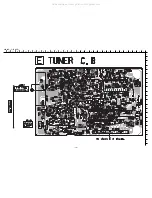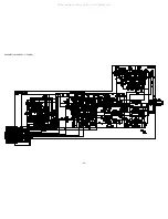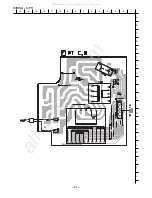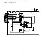
33
ADJUSTMENT (TUNER / DECK / CD / FL)
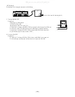
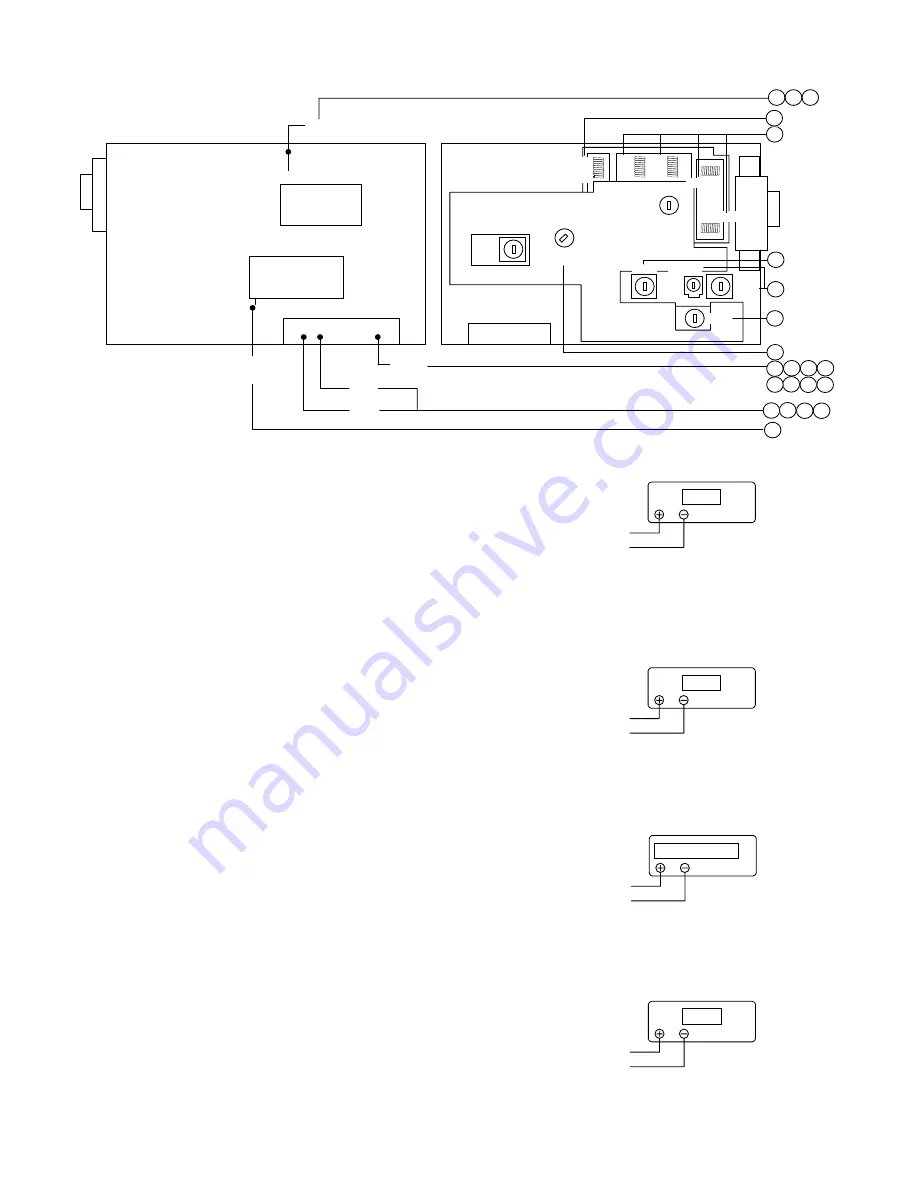
<TUNER SECTION>
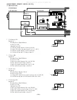
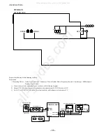
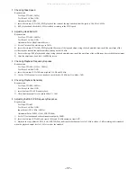
1. VT Adjustment (LW)
Requirement
Measuring Device: Digital Multimeter
Test Point: VT, GND
Adjustment Point: L942
(1) Adjust the reception frequency of the set to 144 kHz.
(2) Adjust L942 until the test point voltage (VT) is 1.3 V ± 0.05 V.
(3) Adjust the reception frequency of the set to 290 kHz.
(4) Check that the test point (VT) voltage is below 8 V.
2. VT Check (MW)
Requirement
Measuring Device: Digital Multimeter
Test Point: VT, GND
(1) Adjust the reception frequency of the set to 1602 kHz.
(2) Check that the test point voltage is below 8 V.
(3) Adjust the reception frequency of the set to 531 kHz.
(4) Check that the test point voltage is above 0.6 V.
3. CLOCK Check
Requirement
Measuring Device: Frequency Counter
Test Point: CLOCK, GND
(1) Change to MW and adjust the reception frequency of the set to 1602 kHz.
(2) Check that the test point (CLOCK) frequency is 2052 kHz ± 45 Hz.
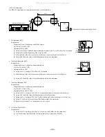
4. VT Adjustment (FM)
Requirement
Measuring Device: Digital Multimeter
Test Point: VT, GND
Adjustment Point: L907
(1) Adjust the reception frequency of the set to 108.0 kHz.
(2) Adjust L907 until the test point voltage (VT) is 7 V ± 0.05V.
(3) Adjust the reception frequency of the set to 87.5 MHz.
(4) Check that the test point voltage is above 0.5 V.
V
DIGITAL MULTIMETER
VT
GND
V
DIGITAL MULTIMETER
VT
GND
V
DIGITAL MULTIMETER
VT
GND
FREQUENCY COUNTER
CLOCK
GND
Hz
Lch
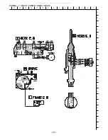
PWB TUNER
PATTERN SIDE
PARTS SIDE
VT
JW970
IC991
IC801
CN991
GND
CLK
Rch
Lch
24
12 11
4
L907
1
2
4
1
6
7
9
4
1
2
3
4
5
6
7
9
5
6
7
9
5
3
L905
L904
L902
L901
L908
L802
L801
L942
TC942
L941
L951
CN991
All manuals and user guides at all-guides.com
Summary of Contents for XR-EM70
Page 13: ...13 SCHEMATIC DIAGRAM 2 MAIN 2 2 AMP SECTION All manuals and user guides at all guides com...
Page 18: ...18 SCHEMATIC DIAGRAM 4 CD CD DRIVE CD LOAD All manuals and user guides at all guides com...
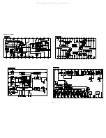
Page 20: ...20 SCHEMATIC DIAGRAM 5 TUNER All manuals and user guides at all guides com...
Page 22: ...22 SCHEMATIC DIAGRAM 6 PT All manuals and user guides at all guides com...
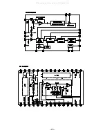
Page 24: ...24 IC BLOCK DIAGRAM All manuals and user guides at all guides com...
Page 25: ...25 All manuals and user guides at all guides com...

