37
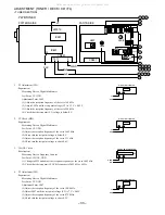
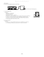
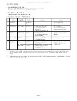
1. Checking Tape Speed
Requirements
Test Tape: TTA-100 (3 kHz)
Test Point: Lch, Rch, GND
Adjustment Point: SFR1
1) Insert the test tape (TTA-100), FWD play back the centre of the tape and check that the speed is 3,000 Hz ± 45 Hz.
2) RVS playback and check that ± 45 Hz is added according to the FWD speed.
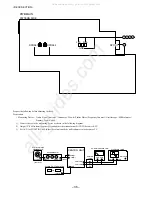
2. Adjusting Head Azimuth
Requirements
Test Tape: TTA-300 (10 kHz)
Test Point: Lch, Rch, GND
Adjustment Point: Head Azimuth Screws
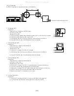
1) Set the V mode of the oscilloscope to ADD.
2) Insert the test tape (TTA-300), FWD playback the centre of the tape and adjust, using the head azimuth screws until the waveform of the
oscilloscope has reached the maximum when playing back at 10 kHz.
3) Reverse the tape, RVS playback and adjust, using the head azimuth screws until the waveform of the oscilloscope has reached the maximum.
4) After the adjustment, bond lock (1600B) the screws.
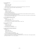
3. Checking Playback Frequency Reponse
Requirements
Test Tape: TTA-300 (315 Hz / 10 kHz)
Test Point: Lch, Rch, GND
1) Insert the test tape (TTA-300) and playback 315 Hz and 10 kHz.
2) Use the 315 Hz output level as a standard, check that the 10 kHz level is within ± 3 dB.
4. Checking Playback Sensitivity
Requirements
Test Tape: TTA-200 (400 Hz)
Test Point: Lch, Rch, GND
1) Insert the tape (TTA-200) and playback.
2) Check that the output level is within 900 mV ± 3 dB.
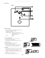
5. Adjusting the REC / PB Frequency Response
Requirements
Test Tape: TTA-602
Test Point: Lch, Rch, GND
Input Point: AUX (1 kHz / 10 kHz)
Adjustment Point: SFR351 (Lch), SFR352 (Rch)
1) Set AUX for function and reduce attenuator output by 20 dB.
2) Insert the test tape (TTA-602) and record 1 kHz and 10 kHz alternately from AUX.
3) Playback the tape, adjust SFR351 (Lch) / SFR352 (Rch) until the playback output level of 1 kHz is within ± 1 dB according to the standard
when the playback output level of 1 kHz is used as the standard.
All manuals and user guides at all-guides.com
Summary of Contents for XR-EM70
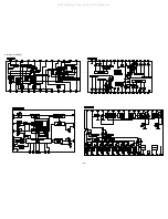
Page 13: ...13 SCHEMATIC DIAGRAM 2 MAIN 2 2 AMP SECTION All manuals and user guides at all guides com...
Page 18: ...18 SCHEMATIC DIAGRAM 4 CD CD DRIVE CD LOAD All manuals and user guides at all guides com...
Page 20: ...20 SCHEMATIC DIAGRAM 5 TUNER All manuals and user guides at all guides com...
Page 22: ...22 SCHEMATIC DIAGRAM 6 PT All manuals and user guides at all guides com...
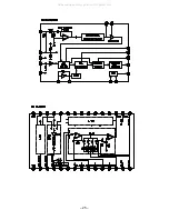
Page 24: ...24 IC BLOCK DIAGRAM All manuals and user guides at all guides com...
Page 25: ...25 All manuals and user guides at all guides com...

