39
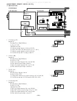
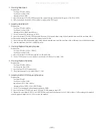
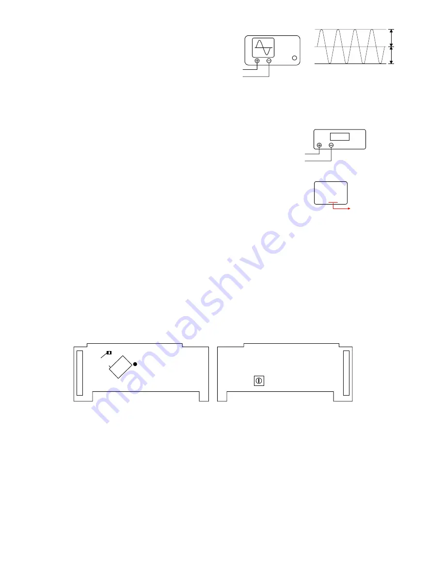
1. Clock Adjustment
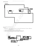
1) Connect an oscilloscope to test point OSC (IC101 77 pin) and GND (IC101 89 pin).
2) Insert the AC plug while pressing POWER and TUNER / BAND buttons.
3) Adjust L101 until the oscilloscope indicates 318.87 Hz ± 0.08 Hz (3.1352 ~ 3.1368 ms)
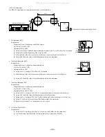
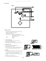
4. Tracking Balance Check
1) Connect the test point (TE), (VC) to the oscilloscope.
2) Playback the second track of TCD-782 and press the PAUSE button.
3) Check that the traverse waveforms of the oscilloscope are up and
down symmetrical.
5.
Play Ability Check
1) Play back the 3rd, 8th, and 13th track of ATD-001. Check that the
noise does not occur and sound skipping does not occur.
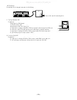
6.
Laser Current Check
* Do not perform this measurement unless the laser is suspected to
be defective.
1) Connect a digital multimeter across the resistor R546 (10 ohm).
2) Play back the TCD-782 and check the DC voltage value on the
digital multimeter.
3) Calculate the laser current (Iop) by dividing the DC voltage across
R546 by the resistor value (R546 = 10 ohm). Check that the laser
current (Iop) is SPEC VALUE ± 10 %.
OSCILLOSCOPE
OUTPUT
TE
VC
DIGITAL MULTIMETER
V
R546
R546
VOLT / DIV: 500mV
TIME / DIV: 1ms
A
B
VC
<FL SECTION>
FL
PWB
IC101
L101
PATTERN SIDE
PARTS SIDE
77
GND
R149
TP
EXAMPLE
KSS-213F
05Y93
DA372
SPEC VALUE
37.2 mA
All manuals and user guides at all-guides.com
Summary of Contents for XR-EM70
Page 13: ...13 SCHEMATIC DIAGRAM 2 MAIN 2 2 AMP SECTION All manuals and user guides at all guides com...
Page 18: ...18 SCHEMATIC DIAGRAM 4 CD CD DRIVE CD LOAD All manuals and user guides at all guides com...
Page 20: ...20 SCHEMATIC DIAGRAM 5 TUNER All manuals and user guides at all guides com...
Page 22: ...22 SCHEMATIC DIAGRAM 6 PT All manuals and user guides at all guides com...
Page 24: ...24 IC BLOCK DIAGRAM All manuals and user guides at all guides com...
Page 25: ...25 All manuals and user guides at all guides com...

