


– 43 –
38
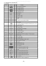
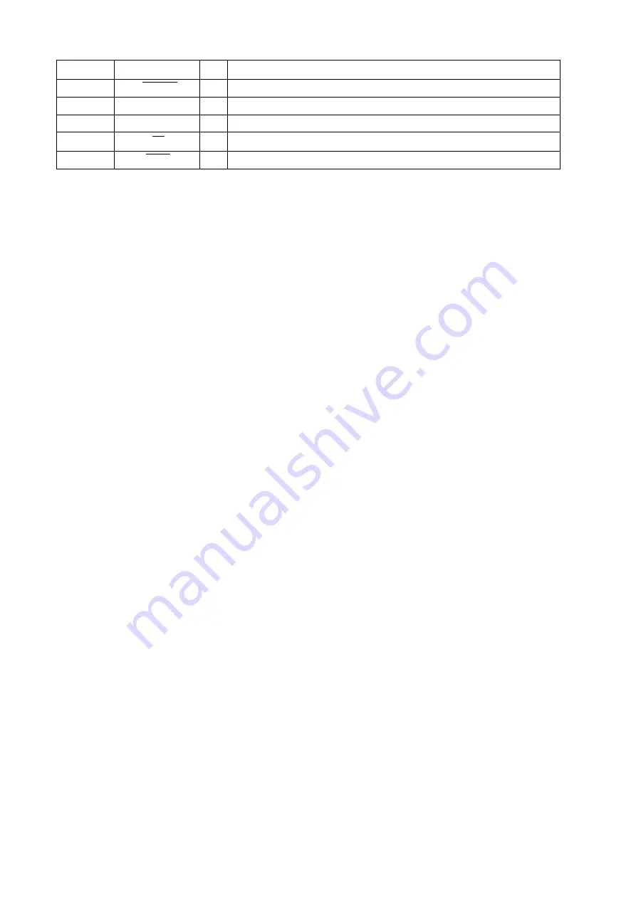
O-DIMMER
O
Ordinarily “H”. When MX-NH2000 is in DIMMER 1 or 2 mode: “L”.
39
I-KEY2
I
KEY input 2. AD input.
40
I-KEY1
I
KEY input 1. AD input.
41
I-MS
I
MS input. AD input.
42
I-HOLD
I
System power supply monitor. AD input.
Description
Pin No.
Pin Name
I/O
*P1Ns 22, 23, 24, 25, and 26 should be “H” when MX-NH2000 is in DIMMER 2 mode.
All manuals and user guides at all-guides.com
Summary of Contents for XR-H2000EZ
Page 13: ... 13 SCHEMATIC DIAGRAM 2 FRONT MX NH2000 All manuals and user guides at all guides com ...
Page 15: ... 15 SCHEMATIC DIAGRAM 3 TUNER MX NH2000 All manuals and user guides at all guides com ...
Page 29: ... 29 SCHEMATIC DIAGRAM MAIN FRONT KEY DX NH2000 All manuals and user guides at all guides com ...
Page 52: ... 52 SCHEMATIC DIAGRAM MAIN GE NH2000 All manuals and user guides at all guides com ...
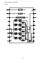
Page 54: ... 54 IC BLOCK DIAGRAM GE NH2000 IC BA3835F All manuals and user guides at all guides com ...


