– 23 –
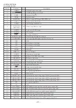
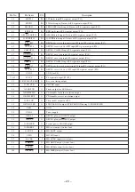
Description
Pin No.
Pin Name
I/O
58
LW/P23
I/O
LW diode input/FL segment output (P23).
59
SW/P22
I/O
SW diode input (Not used)/FL segment output (P22).
60
FM1/P21
I/O
FM1 (OIRT) diode input (Not used)/FL segment output (P21).
61
RDS/P20
I/O
RDS diode input/FL segment output (P20).
62
AM-9K/10K/P19
I/O
AM 10K diode input (Not used)/FL segment output (P19).
63
Q-SUPR/P18
I/O
Q-SUPR diode input (Not used)/FL segment output (P18).
64
REA/P17
I/O
DECK side A record permission SW input/FL segment output (P17).
65
CST1/P16
I/O
DECK 1 cassette detect SW input/FL segment output (P16).
66
CAM1/P15
I/O
DECK 1 CAM SW input/FL segment output (P15).
67
AUTO2/P14
I/O
DECK 2 auto stop input/FL segment output (P14).
68
AUTO1/P13
I/O
DECK 1 auto stop input/FL segment output (P13).
69
CAM2/P12
I/O
DECK 2 CAM SW input/FL segment output (P12).
70
REB/P11
I/O
DECK side B record permission SW input/FL segment output (P11).
71
CST2/P10
I/O
DECK 2 cassette detect SW input/FL segment output (P10).
72
VDD4
–
VDD (for FL).
73~81
P9~P1
O
FL segment output (P9~P1).
82
O-KSCAN/CLKADJ
O
Key scan timing output.
83
O-CD CLK
O
CD CLK ouput.
84
O-LED STB
O
Strobe output for LED driver.
85
O-DISH FWD
O
CD turnable forward revolution output.
86
O-DISH RVS
O
CD turnable reverse revolution output.
87
O-PLL CE
O
Chip enable output for PLL.
88
O-STBY-LED
O
STBY LED ON output (STBY LED ON during O-POWER OFF).
89
VSS2
–
GND.
90
VDD2
–
Power supply.
91
O-SOL1
O
DECK 1 plunger ON/OFF output.
92
O-SOL2
O
DECK 2 plunger ON/OFF output.
93
O-POWER
O
System power ON/OFF output.
94
O-MDRES
O
MD reset output (Active low).
95
O-SOUT
O
MD SOUT output.
96
I-SIN
I
MD SIN input.
97
I-ACLK
I
MD ACLK input (Active low).
98
O-ARDY
O
MD ARDY output (Active low).
99
O-SREQ
O
MD SREQ output (Active low).
100
O-MREQ
O
MD MREQ output (Active low).
Summary of Contents for XR-HG5MD
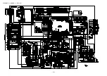
Page 14: ...SCHEMATIC DIAGRAM 1 MAIN 1 2 AMP SECTION 14 ...
Page 15: ...SCHEMATIC DIAGRAM 2 MAIN 2 2 TUNER SECTION 15 ...
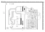
Page 18: ...SCHEMATIC DIAGRAM 3 FRONT 18 ...
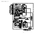
Page 20: ...SCHEMATIC DIAGRAM 4 PT 20 ...
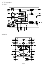
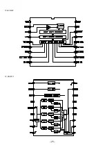
Page 24: ... 24 IC BLOCK DIAGRAM IC LC72131D IC M61500FP ...
Page 25: ... 25 IC BU2092F IC BA3835F ...
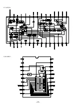
Page 26: ... 26 IC LA1837NL IC BU2099FV ...
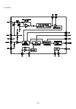
Page 27: ... 27 IC BU1920FS ...
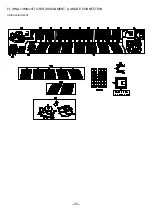
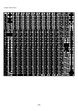
Page 28: ... 28 FL HNA 13MM14T GRID ASSIGNMENT ANODE CONNECTION GRIDASSIGNMENT ...
Page 29: ... 29 ANODECONNECTION ...


