– 6 –
CAUTIONS WHEN ASSEMBLY
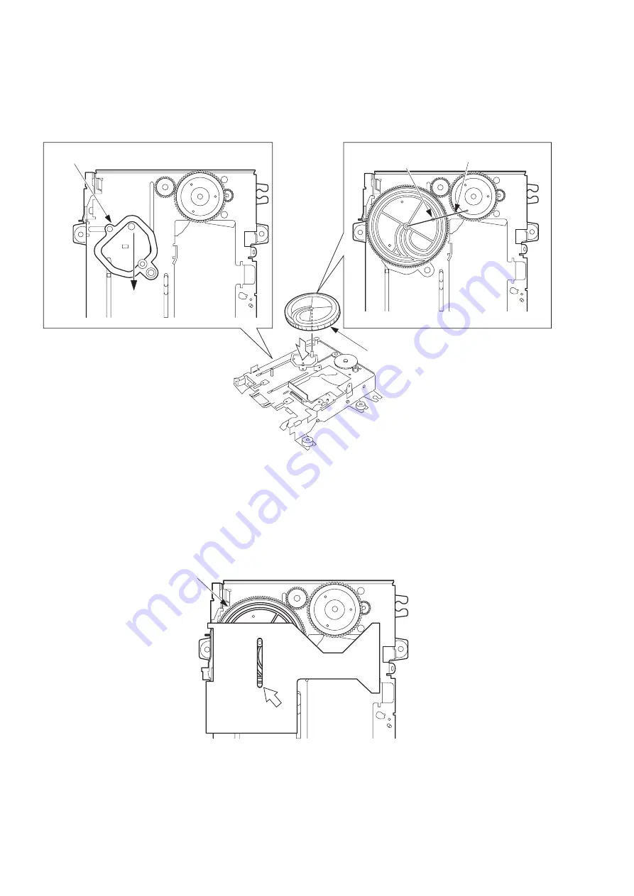
1. Assembling the CAM, LOAD
Move the LEVER ASSY, CAM in the direction of the arrow as far as it can go.
Rotate the CAM, LOAD so that its positioning hole is moved as close as possible to the shaft of the LEVER, SW H.
Attach the CAM, LOAD so that it engages with the teeth of the GEAR, IDLER2.
2. Assembling the PLATE ASSY, SLIDE L
Align the shaft of the PLATE ASSY, SLIDE L with the arrow-marked position of the CAM, LOAD.
CAM, LOAD
positioning hole
Shaft of LEVER, SW H
CAM, LOAD
LEVER ASSY, CAM
CAM, LOAD
Summary of Contents for XR-HG5MD
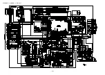
Page 14: ...SCHEMATIC DIAGRAM 1 MAIN 1 2 AMP SECTION 14 ...
Page 15: ...SCHEMATIC DIAGRAM 2 MAIN 2 2 TUNER SECTION 15 ...
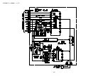
Page 18: ...SCHEMATIC DIAGRAM 3 FRONT 18 ...
Page 20: ...SCHEMATIC DIAGRAM 4 PT 20 ...
Page 24: ... 24 IC BLOCK DIAGRAM IC LC72131D IC M61500FP ...
Page 25: ... 25 IC BU2092F IC BA3835F ...
Page 26: ... 26 IC LA1837NL IC BU2099FV ...
Page 27: ... 27 IC BU1920FS ...
Page 28: ... 28 FL HNA 13MM14T GRID ASSIGNMENT ANODE CONNECTION GRIDASSIGNMENT ...
Page 29: ... 29 ANODECONNECTION ...


