background image

– 8 –

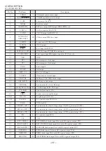
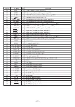
ELECTRICAL  MAIN  PARTS  LIST

DESCRIPTION

REF. NO.

KANRI
NO.

PART NO.

DESCRIPTION

REF. NO.

KANRI
NO.

PART NO.

IC

          8A-DB8-616-010    C-IC,LC876580W-5N90
          87-A21-482-010    IC,RPM6938-H
          87-017-888-080    IC,NJM4558MD
          87-A21-021-040    C-IC,BU2099FV
          87-070-289-040    IC,BU 2092F

          87-A21-031-040    C-IC,BU4551BF
          87-A21-416-040    C-IC,M61500FP
          87-A21-023-040    C-IC,BA3835F
          87-070-127-110    IC,LC72131 D
          87-A20-440-040    C-IC,BU1920FS

          87-A20-913-010    IC,LA1837NL
          87-020-454-010    IC,DN 6851
          87-A21-419-040    C-IC,NJM14558MD-TE2

TRANSISTOR

          87-026-245-080    TR,DTC114ES
          87-026-609-080    TR,KTA1266GR
          87-A30-198-080    TR,KTC3199GR
          89-213-702-010    TR,2SB1370 (1.8W)
          87-026-610-080    TR,KTC3198GR

          87-A30-076-080    C-TR,2SC3052F
          87-A30-075-080    C-TR,2SA1235F
          87-A30-234-080    TR,CSC4115BC
          87-A30-073-080    C-TR,RT1N 141C
          87-A30-186-010    FET,2SK3053

          87-A30-074-080    C-TR,RT1P 141C
          87-026-210-080    CHIP-TR,DTC144EK
          87-A30-190-080    TR,CC5551
          87-A30-137-010    TR,2SD2494
          87-A30-138-010    TR,2SB1625

          87-A30-106-070    C-TR,CMBT5551
          87-A30-107-070    C-TR,CMBT5401
          87-A30-087-080    C-FET,2SK2158
          87-A30-071-080    C-TR,RT1N 144C
          87-A30-256-010    TR,2SD1933

          87-A30-255-010    TR,2SB1342
          87-A30-329-080    TR,CD1585BC
          87-A30-318-080    TR,CSA952K
          87-A30-091-080    FET,2SJ460
          87-A30-090-080    FET,2SK2541

          87-A30-104-080    C-TR,RT1N 441C
          87-A30-085-040    C-TR,CSA1362GR
          87-A30-086-070    C-TR,CSD1306E
          89-327-143-080    C-TR,2SC2714 (0.1W)
          87-A30-072-080    C-TR,RT1P 144C

          87-026-463-080    TR,2SA933S
          89-503-602-080    C-FET,2SK360E

DIODE

          87-A40-736-080    DIODE,1N4148M(SEM)
          87-A40-547-090    DIODE,D5SBA20
          87-070-274-080    DIODE,1N4003 SEM
          87-A40-777-080    ZENER,UZ30BSB
          87-A40-548-090    DIODE,D3SBA20

          87-A40-764-080    ZENER,UZ10BSC
          87-A40-270-080    C-DIODE,MC2838
          87-A40-269-080    C-DIODE,MC2836
          87-A40-749-080    ZENER,UZ5.6BSB
          87-A40-393-090    DIODE,1N5402GW(F20)

          87-A40-767-080    ZENER,UZ12BSC
          87-A40-766-080    ZENER,UZ11BSC
          87-A40-752-080    ZENER,UZ6.2BSC
          87-A40-739-080    ZENER,UZ2.7BSA
          87-A40-802-080    ZENER,UZ5.1BSC

          87-017-149-080    ZENER,HZS6A2L
          87-A40-335-080    ZENER,MTZJ11C T-72

MAIN C.B

 C1       87-012-369-080    C-CAP,S 0.047-50F
 C2       87-012-369-080    C-CAP,S 0.047-50F
 C3       87-012-368-080    C-CAP,S 0.1-50 F
 C4       87-012-368-080    C-CAP,S 0.1-50 F
 C5       87-012-368-080    C-CAP,S 0.1-50 F

 C6       87-012-368-080    C-CAP,S 0.1-50 F
 C9       87-016-658-000    CAP,E 4700-35 M SMG
 C10      87-A10-520-000    CAP,E 3300-35 M SMG
 C11      87-012-368-080    C-CAP,S 0.1-50 F
 C12      87-012-368-080    C-CAP,S 0.1-50 F

 C13      87-012-368-080    C-CAP,S 0.1-50 F
 C21      87-010-385-080    CAP, ELECT 220-25V
 C22      87-010-385-080    CAP, ELECT 220-25V
 C23      87-010-247-080    CAP, ELECT 100-50V
 C24      87-010-247-080    CAP, ELECT 100-50V

 C25      87-010-430-080    CAP, ELECT 100-63
 C26      87-010-263-080    CAP, ELECT 100-10V
 C27      87-010-197-080    CAP, CHIP 0.01 DM
 C29      87-010-247-080    CAP, ELECT 100-50V
 C30      87-010-381-080    CAP, ELECT 330-16V

 C31      87-010-235-080    CAP,E 470-16 SME
 C32      87-010-405-080    CAP, ELECT 10-50V
 C33      87-010-405-080    CAP, ELECT 10-50V
 C34      87-012-368-080    C-CAP,S 0.1-50 F
 C35      87-010-198-080    CAP, CHIP 0.022

 C36      87-010-198-080    CAP, CHIP 0.022
 C40      87-010-112-080    CAP, ELECT 100-16V
 C50      87-010-182-080    C-CAP,S 2200P-50 B
 C51      87-010-180-080    C-CER 1500P
 C61      87-010-260-080    CAP, ELECT 47-25V

 C62      87-010-403-080    CAP, ELECT 3.3-50V
 C91      87-010-401-080    CAP, ELECT 1-50V
 C92      87-010-374-080    CAP, ELECT 47-10V
 C93      87-010-380-080    CAP, ELECT 47-16V
 C101     87-010-178-080    CHIP CAP 1000P

 C102     87-010-178-080    CHIP CAP 1000P
 C103     87-010-402-080    CAP, ELECT 2.2-50V
 C104     87-010-402-080    CAP, ELECT 2.2-50V
 C107     87-010-406-080    CAP, ELECT 22-50V
 C108     87-010-406-080    CAP, ELECT 22-50V

 C109     87-010-322-080    C-CAP,S 100P-50 CH
 C110     87-010-322-080    C-CAP,S 100P-50 CH
 C111     87-010-260-080    CAP, ELECT 47-25V
 C112     87-010-260-080    CAP, ELECT 47-25V
 C113     87-A10-946-080    C-CAP,S 220P-100 J CH

 C114     87-A10-946-080    C-CAP,S 220P-100 J CH
 C117     87-010-400-080    CAP, ELECT 0.47-50V
 C118     87-010-400-080    CAP, ELECT 0.47-50V
 C121     87-010-178-080    CHIP CAP 1000P
 C122     87-010-178-080    CHIP CAP 1000P

 C123     87-010-176-080    C-CAP,S 680P-50 SL
 C124     87-010-176-080    C-CAP,S 680P-50 SL
 C125     87-012-368-080    C-CAP,S 0.1-50 F
 C126     87-012-368-080    C-CAP,S 0.1-50 F
 C127     87-012-368-080    C-CAP,S 0.1-50 F

 C128     87-012-368-080    C-CAP,S 0.1-50 F
 C129     87-010-191-080    C-CAP,S 0.015-50 F
 C130     87-010-191-080    C-CAP,S 0.015-50 F
 C131     87-010-197-080    CAP, CHIP 0.01 DM
 C132     87-010-197-080    CAP, CHIP 0.01 DM

 C133     87-010-197-080    CAP, CHIP 0.01 DM
 C140     87-012-141-080    C-CAP,S 0.22-16 ZF
 C203     87-010-178-080    C-CAP,S 1000P-50 KB
 C204     87-010-178-080    C-CAP,S 1000P-50 KB
 C209     87-010-403-080    CAP, ELECT 3.3-50V

 C210     87-010-403-080    CAP, ELECT 3.3-50V
 C211     87-010-181-080    CAP,CHIP S 1800P
 C212     87-010-181-080    CAP,CHIP S 1800P

Summary of Contents for XR-HG5MD

Page 1: ...vice Manual is the Revision Publishing and replaces Simple Manual XR HG5MD K EZ S M Code No 09 002 423 9T2 If requiring information about the CD mechanism see Service Manual of AZG 1 ZD8RMDM S M Code No 09 001 335 3NA If requiring information about the MD mechanism see Service Manual of AZG 7 DM S M Code No 09 001 338 4N2 XR HG5MD SPEAKER SYSTEM CD CASSEIVER SX WNHG5 CX NHG5MD RC ZAS16 REMOTE CONT...

Page 2: ...deck section Track format 4 tracks 2 channels stereo Frequency response 50 Hz 15000 Hz Recording system AC bias Heads Deck 1 Playback head x 1 Deck 2 Recording Playback head x 1 erase head x 1 Compact disc player section Laser Semiconductor laser λ 780 nm D A converter 1 bit dual Signal to noise ratio 85 dB 1 kHz 0 dB Harmonic distortion 0 05 1 kHz 0 dB Wow and flutter Unmeasurable MD recorder sec...

Page 3: ...ificeras i denna bruksanvising kan användaren utsättas för osynling laserstrålning som överskrider gränsen för laserklass 1 PROTECTION OF EYES FROM LASER BEAM DURING SERVICING CAUTION Use of controls or adjustments or performance of proce dures other than those specified herin may result in hazardous radiation exposure ATTENTION L utillisation de commandes réglages ou procédures autres que ceux sp...

Page 4: ...in power 2 2 2 2 2 Confirm that the main power is turned on and the HOLD terminal of the MICROCOMPUTER keeps the H level or not 3 3 3 3 3 When the HOLD terminal is L level the abnormality detection circuit is judged to be working correctly and the MICROCOMPUTER is judged to be good 1 Forced discharge of electrolytic capacitor of power supply block When repair is going to be attempted in the set th...

Page 5: ... ends of the electrolytic capacitor C113 that is connected to VDD of the MICROCOMPUTER with tweezers 3 3 3 3 3 Connect the AC power cord again If the MICROCOMPUTER returns to the normal operation the MICROCOMPUTER is good Note The reference number or MICROCOMPUTER pin number of transistor Q110 and electrolytic capacitor C113 can change depending on the models Be sure to check the reference numbers...

Page 6: ...ts positioning hole is moved as close as possible to the shaft of the LEVER SW H Attach the CAM LOAD so that it engages with the teeth of the GEAR IDLER2 2 Assembling the PLATE ASSY SLIDE L Align the shaft of the PLATE ASSY SLIDE L with the arrow marked position of the CAM LOAD CAM LOAD positioning hole Shaft of LEVER SW H CAM LOAD LEVER ASSY CAM CAM LOAD ...

Page 7: ...PLATE ASSY SLIDE L BOSS ZZG D b a c CAM LOAD 3 Remove the two screws S SCREW MD TF of C Remove the two screws S SCREW MD T of D Remove the four FFCs and remove the MD MECHANISM 4 Remove the screw VW 1 7 5 of A Remove the HEAD OWH Remove the two screws VTT 2 3 of B Remove the PLATE ASSY SLIDE L and the PLATE SLIDE R in the direction of the arrow 5 Move the ZZG D in the direction of arrow a While pu...

Page 8: ... 080 C CAP S 0 1 50 F C9 87 016 658 000 CAP E 4700 35 M SMG C10 87 A10 520 000 CAP E 3300 35 M SMG C11 87 012 368 080 C CAP S 0 1 50 F C12 87 012 368 080 C CAP S 0 1 50 F C13 87 012 368 080 C CAP S 0 1 50 F C21 87 010 385 080 CAP ELECT 220 25V C22 87 010 385 080 CAP ELECT 220 25V C23 87 010 247 080 CAP ELECT 100 50V C24 87 010 247 080 CAP ELECT 100 50V C25 87 010 430 080 CAP ELECT 100 63 C26 87 01...

Page 9: ...80 CAP 560P C461 87 012 158 080 C CAP S 390P 50 CH C462 87 012 158 080 C CAP S 390P 50 CH C501 87 010 401 080 CAP ELECT 1 50V C502 87 010 401 080 CAP ELECT 1 50V C503 87 010 545 080 CAP E 0 22 50 M 11L SME C504 87 010 545 080 CAP E 0 22 50 M 11L SME C505 87 010 545 080 CAP E 0 22 50 M 11L SME C506 87 010 545 080 CAP E 0 22 50 M 11L SME C507 87 010 196 080 CHIP CAPACITOR 0 1 25 C508 87 010 196 080 ...

Page 10: ... FF CABLE 12P 1 25 FFE801 A8 6ZA 191 130 6ZA 1 FEENM J201 87 A60 483 010 JACK DIA6 3 BLK ST W S KM J203 87 A60 238 010 TERMINAL SP 4P MSC J204 87 A60 886 010 JACK PIN 4P R W BLUE J602 87 A60 881 010 JACK PIN 2P MSP 242V05 PBSN J802 87 A60 403 010 TERMINAL ANT PAL 2P HSP 312V05 JW811 87 008 372 080 FILTER EMI BL OIRNI L101 87 003 383 010 COIL 1UH S L102 87 003 383 010 COIL 1UH S L201 87 003 383 010...

Page 11: ...D SEL6210S RED S301 87 A91 024 180 SW TACT KSHG611BT S302 87 A91 024 180 SW TACT KSHG611BT S303 87 A91 024 180 SW TACT KSHG611BT S304 87 A91 024 180 SW TACT KSHG611BT S305 87 A91 024 180 SW TACT KSHG611BT S306 87 A91 024 180 SW TACT KSHG611BT S307 87 A91 024 180 SW TACT KSHG611BT S308 87 A91 024 180 SW TACT KSHG611BT S309 87 A91 024 180 SW TACT KSHG611BT S310 87 A91 024 180 SW TACT KSHG611BT S311 ...

Page 12: ...PART CODE 0 55 Resistor Code Dimensions mm Symbol 1 16W 1005 5 CJ 1 0 0 5 0 35 104 L t W TRANSISTOR ILLUSTRATION DTC114ES KTC3199 2SA933 CSC4115 KTA1266 KTC3198 CSA952 CD1585 E C B E C B 2SB1370 B C E B 2SA1235 2SC2714 2SC3052 DTC144EK RT1N144C RT1P141C RT1P144C G D S 2SK2158 B C E C E RT1N141C RT1N441C CMBT5551 CMBT5401 CSA1362 CSD1306E 2SD2494 2SB1625 2SD1933 2SB1342 G D S 2SK3053 E C B CC5551 S...

Page 13: ...WIRING 1 MAIN 13 10 11 12 13 14 15 16 17 18 19 20 21 22 23 24 A B C D E F G H I J K L M N O P Q R S T U 1 2 3 4 5 6 7 8 9 25 26 27 28 29 30 31 32 ...

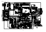
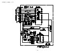
Page 14: ...SCHEMATIC DIAGRAM 1 MAIN 1 2 AMP SECTION 14 ...

Page 15: ...SCHEMATIC DIAGRAM 2 MAIN 2 2 TUNER SECTION 15 ...

Page 16: ... 16 WIRING 2 FRONT 1 2 18 19 20 21 22 23 24 25 26 27 28 29 30 31 32 A B C D E F G H I J K L M N O P Q R S T U 17 16 15 14 13 12 11 10 9 8 7 6 5 4 3 2 1 ...

Page 17: ... 17 15 14 13 12 11 10 9 8 7 6 5 4 3 2 1 A B C D E F G H I J K L M N O P Q R S T U 16 17 18 19 20 21 22 23 24 25 26 27 28 29 30 31 32 WIRING 2 FRONT 2 2 ...

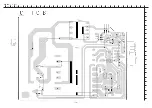
Page 18: ...SCHEMATIC DIAGRAM 3 FRONT 18 ...

Page 19: ...WIRING 3 PT 19 10 11 12 13 14 15 16 17 18 19 20 21 22 23 24 A B C D E F G H I J K L M N O P Q R S T U 1 2 3 4 5 6 7 8 9 25 26 27 28 29 30 31 32 ...

Page 20: ...SCHEMATIC DIAGRAM 4 PT 20 ...

Page 21: ...WIRING 4 DECK 21 10 11 12 13 14 15 16 17 18 19 20 21 22 23 24 A B C D E F G H I J K L M N O P Q R S T U 1 2 3 4 5 6 7 8 9 25 26 27 28 29 30 31 32 ...

Page 22: ...er input 26 I SPEANA I Spectrum analyzer level AD input 27 I WRQ I RDS CLK I O CD WRQ input RDS CLK input 28 I TM BASE I Standard time input 8Hz 29 I RMC I System remote controller input 30 42 G13 G1 O FL grid output G13 G1 43 45 P36 P34 O FL segment output P36 P34 46 VDD3 VDD for FL 47 SPEANA A P33 O Spectrum analyzer band change output A FL segment output P33 48 SPEANA B P32 O Spectrum analyzer ...

Page 23: ... SW input FL segment output P12 70 REB P11 I O DECK side B record permission SW input FL segment output P11 71 CST2 P10 I O DECK 2 cassette detect SW input FL segment output P10 72 VDD4 VDD for FL 73 81 P9 P1 O FL segment output P9 P1 82 O KSCAN CLKADJ O Key scan timing output 83 O CD CLK O CD CLK ouput 84 O LED STB O Strobe output for LED driver 85 O DISH FWD O CD turnable forward revolution outp...

Page 24: ... 24 IC BLOCK DIAGRAM IC LC72131D IC M61500FP ...

Page 25: ... 25 IC BU2092F IC BA3835F ...

Page 26: ... 26 IC LA1837NL IC BU2099FV ...

Page 27: ... 27 IC BU1920FS ...

Page 28: ... 28 FL HNA 13MM14T GRID ASSIGNMENT ANODE CONNECTION GRIDASSIGNMENT ...

Page 29: ... 29 ANODECONNECTION ...

Page 30: ...DC TP1 VT TP2 CLK TP8 LCH TP9 RCH 2 L772 TP3 DC 3 3 1 3 6 1 GND 13 14 4 6 3 3 5 9 10 11 A MAIN C B 8 15 SFR451 SFR452 16 SFR1 DECK 1 P HEAD DECK 2 R P E HEAD DECK C B D 12 13 13 FWD REV FL101 CN101 IC101 TP11 CLK TP12 GND L151 B FRONT C B 16 17 L942 L941 TC942 4 5 7 ...

Page 31: ...e level at 290kHz is adjusted to MAX by TC942 6 AM IF Adjustment Settings Test point TP8 Lch TP9 Rch Adjustment location L772 450kHz 7 FM VT Check Settings Test point TP1 VT Method Set to FM 108 0MHz and check that the test point is less than 8 0V Then set to FM 87 5MHz and check that the test point is more than 0 5V 8 FM Tracking Check Settings Test point TP8 Lch TP9 Rch Method Set to FM 98 0MHz ...

Page 32: ...TP8 Lch TP9 Rch Method Play back the test tape and check that the output level of the test point is 100mV 3dB 16 REC PB Frequency Response Adjustment DECK 2 Settings Test tape TTA 602 Test point TP8 Lch TP9 Rch Input signal 1kHz 8kHz LINE IN Adjustment location SFR451 Lch SFR452 Rch Method Apply a 1kHz signal and REC mode Then adjust OSC attenuator so that the output level at the TP8 TP9 becomes 2...

Page 33: ...LAT EARTH MECHA 27 29 28 30 9 24 25 31 32 34 35 28 29 36 23 26 37 38 39 40 41 42 44 61 43 56 57 45 62 46 48 47 49 50 51 52 44 53 55 54 P C B P C B P C B HT SINK S HT SINK TRS HT SINK SUB HT SINK FIN HT SINK FIN HT SINK FIN 58 37 39 H A A A A A A A A A J I G G E A A A A A E D C C B F A A A A A A H A a a b b c c B 33 60 60 60 A 59 ...

Page 34: ...0 PLATE LOCK 29 86 NF9 224 010 SPR C LOCK 30 82 NF5 219 010 SPR T EJECT 2 SIN 31 88 915 121 110 FF CABLE 15P 1 25 32 8A DB8 023 010 KEY T BASS 33 8A DB8 025 010 KEY RDS 34 8A DB8 020 010 KEY ECO 35 8A DB8 024 010 KEY REC 36 87 NF4 217 110 HLDR LOCK 2 37 88 907 301 110 FF CABLE 7P 1 25 38 88 913 271 110 FF CABLE 13P 1 25 39 87 NB7 615 010 CONN ASSY 2P SHIELDPH PH 40 8A NF8 007 010 PANEL LEFT V 2 41...

Page 35: ... 2 C B DECK 2 PH DECK 1 RPH DECK 2 DECK 2 DECK 2 36 DECK 1 B B A 2ZM3MK2 PR4N YPR4N B B 31 38 39 40 34 33 35 43 45 41 41 44 49 47 48 46 C C 30 8 DECK 1 D 18 52 51 D D CAPSTAN N 2 2 41 5 DECK C B 50 50 A CUSH G DIA3 7 8 3 2 A 37 32 C E CUSH G DIA3 7 8 3 2 CAPSTAN N 2 2 41 7 SH 1 63 3 2 0 5 SLT SH BELT D2 2ZM3MK2 PR4N BOTTOM SIDE 2000 3 6 YPR4N ...

Page 36: ...243 010 LVR STOP 28 82 ZM1 259 210 SPR T PINCH R 29 82 ZM1 240 110 LVR REC 30 80 ZM6 243 010 SH 1 75 3 6 0 5 SLT 31 82 ZM1 255 310 SPR E LVR DIR 32 82 ZM3 305 210 GEAR CAM M2 33 82 ZM1 227 310 LVR TRIG 34 82 ZM3 306 110 LVR FR M2 35 82 ZM1 265 310 SPR E TRIG 36 82 ZM3 339 110 SHAFT COUPLER N3 37 86 ZM1 206 010 BELT MAIN L 38 82 ZM1 322 010 SPR T FR 60 39 82 ZM1 220 210 GEAR IDLER 40 82 ZM3 616 010...

Page 37: ... R 82 ZM1 265 119 SPR E TRIG 82 ZM1 255 319 SPR E LER DIR 82 ZM1 258 110 SPR T PINCH L 82 ZM1 213 019 SPR T HEAD 82 ZM1 269 219 SPR T BRG 82 ZM1 214 010 SPR T DIR 82 ZM1 285 310 SPR C BT L 82 ZM1 219 119 SPR T LINK 82 ZM1 257 019 SPR T CAS 82 ZM1 218 019 SPR E HB 82 ZM1 244 410 SPR C BT ...

Page 38: ...rning to clockwise direction until click sound comes out Remove the grill frame and four pieces of rubber caps by pulling out with a flat bladed screwdriver Remove the screws from hole where installed rubber caps Insert a flat bladed screwdriver into the position indicated by the arrows and remove the panel Re move the screws of each speaker unit and then remove the speaker units TOOLS 1 Plastic h...

Page 39: ...OTECTOR 4 88 NS5 610 010 CORD SPKR 5 88 NS5 611 010 CORD SPKR B L 6 8Z NSY 003 010 CORD BUSH 7 88 NS3 029 010 CORD BUSH L 8 8Z NS7 602 010 SPKR W 160 9 8Z NSY 604 010 SPKR M 100 10 8Z NSY 608 010 SPKR CERAMIC ASSY 11 8A DS8 005 010 GRILLE FRAME ASSY 1 8A DB8 905 010 IB K E M K 1 8A DB8 906 010 IB EZ 9L M EZ 2 8Z NB8 704 010 RC UNIT RC ZAS16 3 87 043 106 010 ANT FM 1007AWG 4 87 006 225 010 ANT LOOP...

Page 40: ...2 11 IKENOHATA 1 CHOME TAITO KU TOKYO 110 JAPAN TEL 03 3827 3111 Printed in Singapore 9420208 0251431 ...

Page 41: ...OM be sure to identify a CD mechanism with reference to the table below µ Determine a type of CD mechanism by a pick up that is mounted 1 AZG 1 ZD3 ZD4 KSS 213F is mounted 2 AZG 1 ZD8 KSM 880 is mounted KSS 213F KSM 880 Servo IC Digital Servo 8A DB8 616 110 8A DB8 616 010 LA9235M LC78641E LC876580W 5R43 LC876580W 5N90 Ref Parts Code Description Remarks IC101 8A DB8 616 010 C IC LC876580W 5N90 AZG ...

Reviews: