CD ADJUSTMENT
・
Perform the adjustments after the main unit enters the test mode.
・
Place the CD mechanism on level ground.
・
Equipment and tools required
Measuring equipment
Digital multi-meter
Jitter meter (KIKUSUI 6235)
Test disc: TCD-782
ATD-001
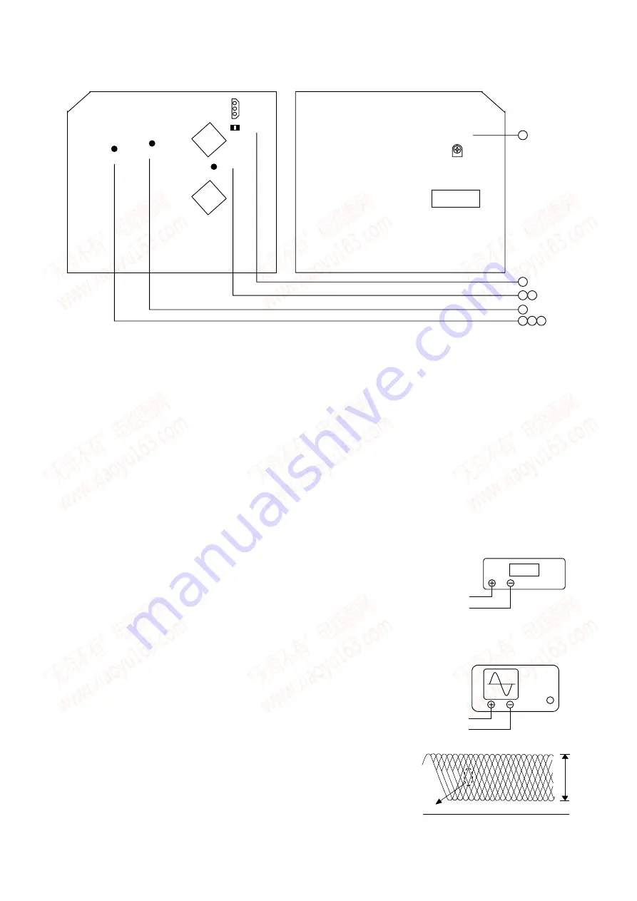
1.FOCUS BAIS ADJUSTMENT
1)
Connect the digital multi-meter to the test point FE and Vref.
2)
Play back the 2
nd
track of TCD-782.
Adjust SFR430 until the digital multi-meter indicates 0
±
10mV.
Connect oscilloscope to the test point RF SW and Vref.
3) Check that the RF waveform has the maxmum amplitude and the center of the wedge
OUTPUT
OSCILLOSCOPE
RF SW
Vref
CD PWB
PATTERN SIDE
PARTS SIDE
SFR430
FE
R401
1
2
1 2 3
5
3
IC401
IC402
R402
IC403
Vref
RF SW
1
V
DIGITAL MULTIMETER
FE
Vref
VOLT / DIV: 500mV
TIME / DIV: 0.2
µ
s
EYE PATTERN
must be CLEAR and MAX
Approx.
1.8
±
0.3V
p.p
-31-
www. xiaoyu163. com
QQ 376315150
9
9
2
8
9
4
2
9
8
TEL 13942296513
9
9
2
8
9
4
2
9
8
0
5
1
5
1
3
6
7
3
Q
Q
TEL 13942296513 QQ 376315150 892498299
TEL 13942296513 QQ 376315150 892498299


