-30-
ELECTRICAL ADJUSTMENT-8/13 (HS MODEL)
DECK ADJUSTMENT
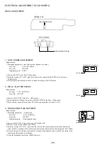
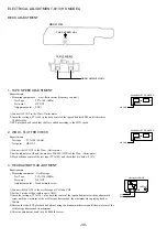
1. TAPE SPEED ADJUSTMENT
Requirements
• Measuring equipments : wow-flutter meter (frequency counter )
Test Tape
: TTA-100 (3KHz)
Test point
: HP OUT
Adjustment point : SFR1
1) Connect HP OUT to the Wow - flutter meter.
2) Insert the test tape (TTA-100), play back center of the tape and adjust SFR1 until it becomes
3,000Hz±5Hz.
3) RVS playback and check that ±45Hz is added according to the FWD speed.
2. WOW - FLUTTER CHECK
Requirements
Test tape
: TTA-100 (3KHz)
Test point : HP OUT
1) Connect the HP OUT to the Wow - flutter meter.
2) Set the indicator to JIS and the mode to W RMS (WTD) of the Wow - flitter meter.
3) Play back thee center of the test tape (TTA-100) and check that it is below 0.35%.
3. HEAD AZIMUTH ADJUSTMENT
Requirements
• Measuring equipment : Oscilloscope
Test Tape
: TTA-330 (8KHz)
Test point
: HP OUT
Adjustment point : Head azimuth screw
1) Connect the HP OUT to the oscilloscope of CH1 and CH2.
2) Set the V mode of the oscilloscope to ADD.
3) Insert the test tape (TTA-330) , play back the center of the tape and adjustment the head azimuth
screw until the waveform of the oscilloscope has reached the maximum when playing back at
10KHz.
4) Reverse the tape, RVS playback and adjust, using the head azimuth screws until the waveform of the
oscilloscope has reached its maximum.
5) After the adjustment, bond lock (1600B) the screw.
TAPE SPEED ADJ.
HEAD AZIMUTH ADJ.
DECK C.B.
Hz
WOW&FLUTTER METER
HP OUT
%
INPUT
Hz
WOW&FLUTTER METER
HP OUT
%
INPUT
OUTPUT
OSCILLOSCOPE
Lch
Rch
CH1
CH2
Summary of Contents for XR-M161HS(S)
Page 23: ... 22 FL ZCL 8 GRID ASSIGNMENT ANODE CONNECTION 1 1 GRID ASSIGNMENT ANODE CONNECTION ...
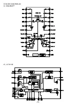
Page 39: ... 38 IC M62495AFP AUTO RESET IC BLOCK DIAGRAM 2 2 IC LC72131D ...
Page 51: ... 50 CD MECHANISM EXPLODED VIEW 1 2 DA 11T3C A M2 PIN 3 SW1 MOTOR C B 4 3 2 1 ...
Page 53: ... 52 CD MECHANISM EXPLODED VIEW 2 2 KSM 213CDM 1 2 COVER 3 4 5 SPINDLE MOTOR M3 MOTOR C B A M2 ...

