61
Note:
1. If operation of the mechanism shows any abnormality during the test mode, disconnect the AC plug immediately.
2. The playback and recording operations are not possible during the test mode.
3. There can be a case that a disc cannot be inserted. In such a case, insert the disc a little and press the “CD
™
MD DIRECT
REC” button. The disc can be inserted to the very end.
4. “REC Analog” is switched to “REC Digital” by pressing the following buttons in order:
9
button
™
;
button
™
0
button
(main unit).
2-2. How to Exit the CD Test Mode
1) Press the “MD EJECT” button to remove the disc.
2) Disconnect the AC plug from the power outlet.
*
If the machine exits the MD test mode by any methods other than the procedure as described above, the machine may
operate abnormally when the POWER is turned on next time.
In such a case, disconnect the AC plug.
2-3. Operation Check Mode
1) Checks after the test mode has started up
The following playback audio circuits can be checked.
•
The circuits that can be checked: ..................... DAC, LINE AMP, HEADPHONES AMP
•
Output level: .................................................... 1 kHz, -23 dB
2) Switch status check
ON/OFF statuses of the respective switches of the machine and mechanism can be checked on display.
2-4. How to Switch to Servo Standby Mode
When the MD test mode has been established, the mode is changed to the servo standby mode and “ALL SV OFF” is displayed
by pressing the
9
(CLEAR) button. The following various check modes can be entered from this mode. Returns to “ALL SV
OFF” by pressing the
9
button.
L
A L S V O F F
2-5. Checking the Sled Operation
1) Pickup moves to the outmost track by pressing the
6
(F.SKIP) in the “ALL SV OFF” state. The message “T.SLED FWD”
is displayed.
2) Pickup moves to the innermost track by pressing the
5
(B.SKIP) in the “ALL SV OFF” state. The message “T.SLED
FWD” is displayed.
2-6. Checking the Laser Output
1) The laser power output level can be switched by every pressing of the “EDIT” (SHIFT+9) in the “ALL SV OFF state”.
The laser power output is repeatedly changed in the following order of: OFF
™
LASER READ
™
LASER1/2
™
LASER
WRITE
™
OFF. The displays are shown as described by the following table.
2) After confirming the message, press the
9
button to turn off the “ALL SV OFF” display.
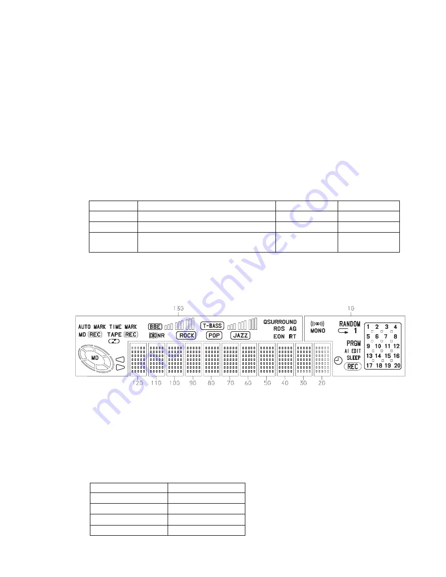
MODE
Indication on display
OFF
ALL SV OFF
LASER READ
LASER READ
LASER 1/2 WRITE
LASER 1/2
LASER WRITE
LASER WRITE
Switch Name
Switch State
Indication on Display
Usable disc
REC PROTECT
When the write-protection tab of a disc is closed to ON ROCK
Record/playback disc
REFRECT
When the high reflection disc (CD) is used
POP
Playback only disc
INNER
When the pickup is the positioned at the innermost
JAZZ
—
track (when the LIMIT switch is ON)
Summary of Contents for XR-MD200
Page 6: ...6 DISASSEMBLY INSTRUCTIONS 1 Remove the two screws 2 Remove the two screws 1 2 ...
Page 13: ...14 13 BLOCK DIAGRAM IC301 LC866532A ...
Page 14: ...1 2 3 4 5 6 7 8 9 10 11 12 13 14 A B C D E F G H I J K 16 15 WIRING 1 POWER AMP AC 230V 50Hz ...
Page 15: ...18 17 SCHEMATIC DIAGRAM 1 POWER AMP Q261 262 MUTE R261 22k R262 22k 220k 220k 1000p 1000p ...
Page 16: ...1 2 3 4 5 6 7 8 9 10 11 12 13 14 A B C D E F G H I J K 20 19 WIRING 2 FRONT ...
Page 17: ...22 21 SCHEMATIC DIAGRAM 2 FRONT IC301 LC866532A 5L31 ...
Page 28: ...40 39 BLOCK DIAGRAM 1 CD ...
Page 29: ...42 41 BLOCK DIAGRAM 2 MD TO MAIN C B CN502 TO CD C B CN6 ...
Page 30: ...44 43 WIRING 1 CD 14 13 12 11 10 9 8 7 6 5 4 3 2 1 A B C D E F G H I J CD C B COMPONENT SIDE ...
Page 31: ...46 45 1 2 3 4 5 6 7 8 9 10 11 12 13 14 A B C D E F G H I J TP3 CD C B CONDUCTOR SIDE ...
Page 32: ...48 47 SCHEMATIC DIAGRAM 1 CD 1 2 DTC114TK ...
Page 33: ...50 49 SCHEMATIC DIAGRAM 2 CD 2 2 RESET 5M36 ...
Page 34: ...1 2 3 4 5 6 7 8 9 10 11 12 13 14 A B C D E F G H I J K 52 51 WIRING 2 FUNCTION ...
Page 35: ...54 53 SCHEMATIC DIAGRAM 3 FUNCTION ...
Page 59: ...81 IC BA5936 Rog CURRENT DETECTOR TERMINAL IC BA5970FP IC BA6417F ...
Page 60: ...82 IC BD7910FV IC AK4519VF ...
Page 72: ...931196 Printed in Singapore 2 11 IKENOHATA 1 CHOME TAITO KU TOKYO 110 JAPAN TEL 03 3827 3111 ...


