15
CD TEST MODE
1.
Starting Up the CD Test Mode
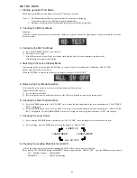
While pressing the “CD” button, connect the AC plug to the power outlet. When the CD test mode starts up, all
displays turn on.
2.
How to Release the CD Test Mode
To release the CD test mode, press the “POWER” button or the function buttons other than the “CD” button, or
disconnect the
AC plug from the power outlet.
3.
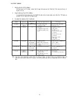
Function Description of the Test Mode
Note: If the focus search operation is continued for 10 minutes or longer, the driver IC heats up sufficiently to trigger the
protection circuit, which stops the CD system. Turn off the main power and re-start operation about 10 minutes
later.
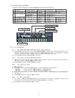
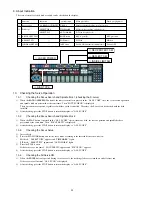
MODE
Start mode
Focus search mode
Play mode
Traverse mode
Sled mode
Operation
CD key + AC
plug IN
STOP key
PLAY key
PAUSE key
F.SKIP key
B.SKIP key
Indication on
display
All indicators light
CD
Track No. and
playing time
(spectrum analyzer)
Track No. and
playing time
CD TEST
Function and movement
• CD TEST mode starts
• All indicators light
• LD lights
• Continuous focus search
• Continuous spindle motor
kick
• Normal playback
• When TOC reading is not
possible, the focus search
continues
• Tracking servo is turned off
• The pickup moves to the
innermost track
• The pickup moves to the
outermost track
Check item
• Check all indicators light
• Microprocessor
• DATA BUS LINE
• APC circuit
• LASER current
• Check the focus search
waveform
• Check the focus error
waveform
• Focus servo circuit
• DRF output
• Spindle servo line
• Same checks as shown in the
above column
• Each servo circuit
• Check the tracking error
waveform
• Tracking circuit
• Sled circuit
• Mechanism (gear and motor)
Summary of Contents for XR-MD510
Page 5: ... 5 ...
Page 15: ... 15 SCHEMATIC DIAGRAM 1 MAIN PT1 PT2 RELAY ...
Page 17: ... 17 SCHEMATIC DIAGRAM 2 FRONT SW 1 SW 2 FACE A FACE B FACE C DECK ...
Page 20: ... 20 SCHEMATIC DIAGRAM 3 CD CD LOAD CD DRIVE ...
Page 22: ... 22 SCHEMATIC DIAGRAM 4 D TUNER ...
Page 24: ... 24 SCHEMATIC DIAGRAM 5 K TUNER ...
Page 26: ... 26 SCHEMATIC DIAGRAM 6 EZ TUNER ...
Page 29: ... 29 IC BLOCK DIAGRAM IC BA5936S IC BU2099FV ...
Page 30: ... 30 IC BU2092F IC BU1920FS ...
Page 31: ... 31 IC MM1454XFBE IC LA1837NL ...
Page 32: ... 32 IC TA2040AF IC HA12211 ...
Page 33: ... 33 IC CXA1553P IC LC72131D ...
Page 34: ... 34 IC BD3876KS2 ...
Page 38: ... 38 8 SFR130 TP3 VREF TP2 FE C CD C B L201 7 TP1 K SCAN GND IC201 7 B FRONT C B ...
Page 43: ... 43 98 O ARDY O 99 O SREQ O 100 I MREQ I ja ja 01234 ja 0123 fLl ...
Page 55: ... 55 FL 13 ST 44GNK ACJ 4 GRID ASSIGNMENT ANODE CONNECTION GRID ASSIGNMENT ...
Page 56: ... 56 ANODE CONNECTION ...

