22
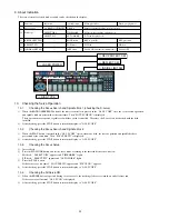
9. About Indication
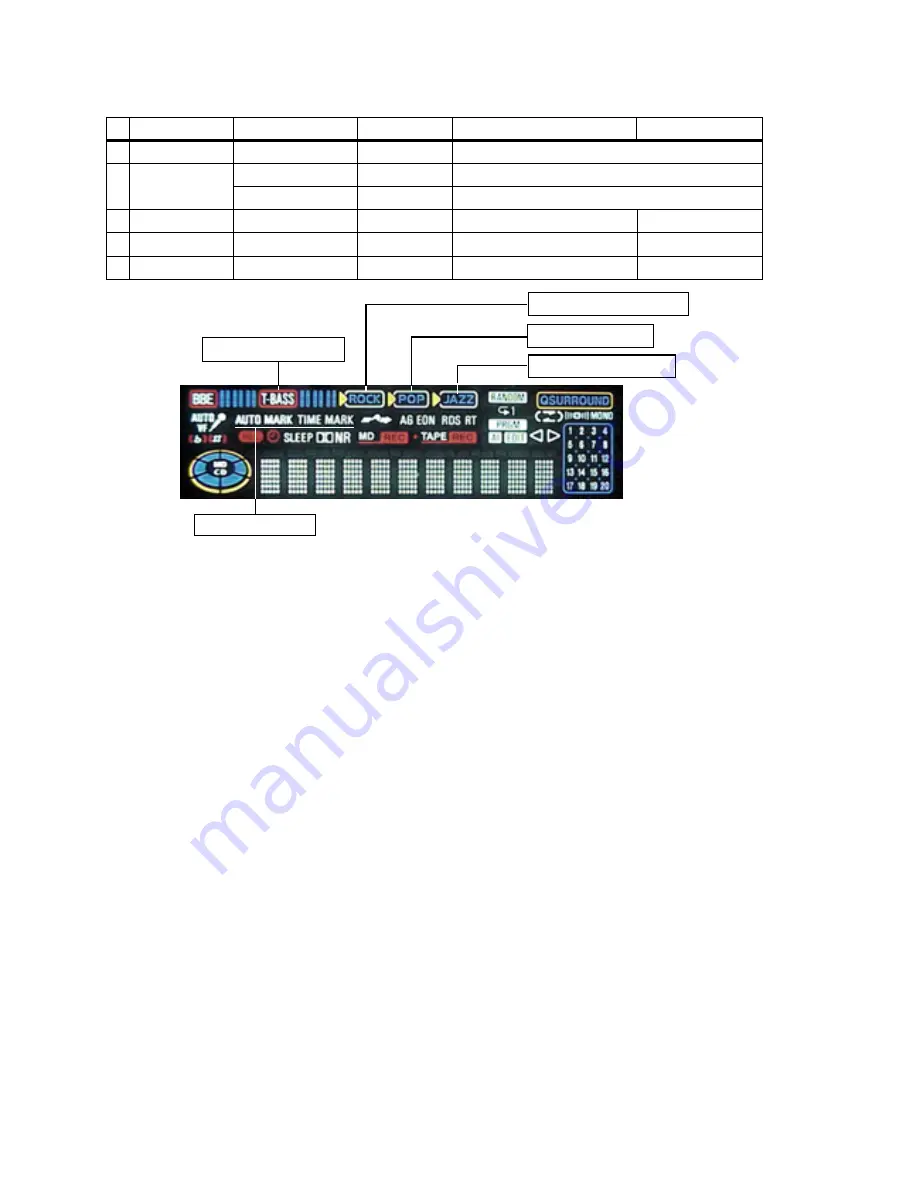
The state of circuit, selected disk or switch can be checked on the display.
10.
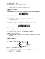
Checking the Servo Operation
10-1.
Checking the Focus Search and Spindle Kick 1 (checking the S-curve)
1)
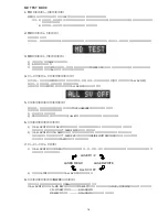
When the RANDOM/REPEAT button of the remote controller is pressed in the “ALL SV OFF” state, the focus search operation
and spindle kick are performed at the same time. Then “FOCUS CHECK” is displayed.
These operations are repeated regardless of whether a disk is installed. Therefore, the S-curve can be checked with the disk
installed.
2)
After checking, press the STOP button to return the display to “ALL SV OFF”.
10-2.
Checking the Focus Search and Spindle Kick 2
1)
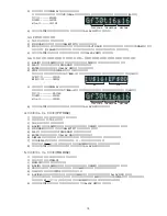
When the PLAY button is pressed in the “ALL SV OFF” state without any disk, the search operation and spindle kick are
performed at the same time. Then “FOCUS SRCH” is displayed.
2)
After checking, press the STOP button to return the display to “ALL SV OFF”.
10-3.
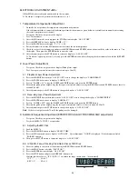
Checking the Focus Servo
1)
Insert a disk.
2)
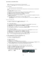
Press the MD MODE button and set the servo mode according to the inserted disk as shown below.
•
MO disk: “ SELECT GRV” appears and “TIMEMARK” lights.
•
PIT disk: “ SELECT PIT” appears and “AUTOMARK” lights.
3)
Press the PLAY button.
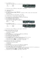
If the focus servo is normal, “ FOCUS SRCH” appears and “FOCUS ON!” appears.
4)
After checking, press the STOP button to return the display to “ALL SV OFF”.
10-4.
Checking the All Servo ON
1)
When the ENTER button is pressed during focus servo off, the tracking sled servo is turned on and all servos run.
If the servos are all normal, “ALL SV ON” is displayed.
2)
After checking, press the STOP button to return the display to “ALL SV OFF”.
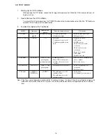
1
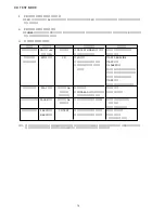
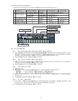
LASER POWER
5
INSIDE LIMIT SW
4
REFLECT SW
3
REC PROTECT SW
2
DISC TYPE
Function
Laser power
Disk type
REC PROTECT SW
REFLECT SW
INSIDE LIMIT SW
Indication
LA READ-1/2-WRITET
SELECT GRV
SELECT PIT
—
—
—
pict indication
T-BASS
TIME MARK
AUTO MARK
ROCK frame
POP frame
JAZZ frame
When pict lights
When pict glights off
Displayed using the three-step level meter
MO disk (for recording and playback)
PIT disk (for playback)
REC is possible.
REC protection
PIT disk
MO disc
Switch ON (innermost circumference)
Switch OFF
1
2
3
4
5
Summary of Contents for XR-MD510
Page 5: ... 5 ...
Page 15: ... 15 SCHEMATIC DIAGRAM 1 MAIN PT1 PT2 RELAY ...
Page 17: ... 17 SCHEMATIC DIAGRAM 2 FRONT SW 1 SW 2 FACE A FACE B FACE C DECK ...
Page 20: ... 20 SCHEMATIC DIAGRAM 3 CD CD LOAD CD DRIVE ...
Page 22: ... 22 SCHEMATIC DIAGRAM 4 D TUNER ...
Page 24: ... 24 SCHEMATIC DIAGRAM 5 K TUNER ...
Page 26: ... 26 SCHEMATIC DIAGRAM 6 EZ TUNER ...
Page 29: ... 29 IC BLOCK DIAGRAM IC BA5936S IC BU2099FV ...
Page 30: ... 30 IC BU2092F IC BU1920FS ...
Page 31: ... 31 IC MM1454XFBE IC LA1837NL ...
Page 32: ... 32 IC TA2040AF IC HA12211 ...
Page 33: ... 33 IC CXA1553P IC LC72131D ...
Page 34: ... 34 IC BD3876KS2 ...
Page 38: ... 38 8 SFR130 TP3 VREF TP2 FE C CD C B L201 7 TP1 K SCAN GND IC201 7 B FRONT C B ...
Page 43: ... 43 98 O ARDY O 99 O SREQ O 100 I MREQ I ja ja 01234 ja 0123 fLl ...
Page 55: ... 55 FL 13 ST 44GNK ACJ 4 GRID ASSIGNMENT ANODE CONNECTION GRID ASSIGNMENT ...
Page 56: ... 56 ANODE CONNECTION ...

