12G-AMA v1.0 10 www.aja.com
Chapter 2 – Operation
Default Operational Settings
The 12G-AMA converter ships from the factory with the following configuration:
• Local (DIP switch) control.
• Input analog audio channels 1-4 are embedded to SDI output channels 1-4,
overwriting any existing embedded audio.
• Input SDI embedded audio channels 1-4 are disembedded to analog audio
output channels 1-4.
• All HANC packets pass from SDI input to output, except for embedded output
audio channels 1-4.
• Analog audio operating level is set to 0 dBfs = +24 dBu (Pro 1).
If these settings apply to your requirements, you can simply connect the video
and audio input and output signal cables and power up the unit.
For other applications, you can configure the unit using its DIP switch settings, or
by using the Mini-Config application and a PC or Mac via USB. Analog audio levels
as well as video input source and stream selection can only be set using Mini-
Config.
DIP Switches
The 12G-AMA DIP switches configure the audio embedding and disembedding
functions, and control ancillary data.
DIP Switch Settings
DIP switch settings used to configure various functions are described below.
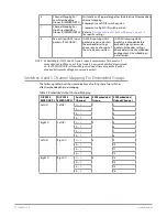
Table 2. 12G-AMA DIP Switch Setting Descriptions
SWITCH FUNCTION
DIP Set LEFT (default)
DIP Set RIGHT
1
Control
Selects Local (DIP), and
blocks Mini-Config control.
Selects Remote (Mini-Config),
and disables DIP switches 2-8.
2
Audio Embedding for
Channels 1/2 (EMBD 1/2)
(ON) Overwrite or embed
new channel 1/2 packets.
(OFF) If SW 8 is set to ON: Pass
any channel 1/2 packets from
input SDI.
If SW 8 is set to OFF: Delete all
packets from input SDI.
3
Audio Embedding for
Channels 3/4 (EMDB 3/4)
(ON) Overwrite or embed
new channel 3/4 packets.
(OFF) If SW 8 is set to ON: Pass
any channel 3/4 packets from
input SDI.
If SW 8 is set to OFF: Delete all
packets from input SDI.
4
Channel Mapping For
Low Embedded Groups
(EMBD GRP L)
Switches 4 and 5 operate together to determine Embedded
channel mapping.
0 represents a Left DIP switch position
1 represents a Right DIP switch position
Refer to
"Embedded Output Channel Mapping" on page 11
for
specific settings.
5
Channel Mapping For
High Embedded Groups
(EMBD GRP H)


