background image


6


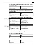
Switch 7—Configure Automatic Gain Control (AGC)


:


Switch 8—Turn Test Pattern Output ON/OFF


:


Installation 


Typically, D10AD installation consists of the following:


1.


disc5VDC from the convertor 


2.


configure the DIP switch for the desired equipment configuration and video formats


3.


connect video equipment to the convertor BNCs


4.


apply +5VDC power to the converter (AJA power supply model DWP)


Specifications


ON

OFF


Automatic Gain ON

Automatic Gain Off (Unity Gain)


ON

OFF


Internal color bars are output

Disables test pattern output (normal video 
operation)


Item

Specification


Serial Outputs

SDI (SMPTE 259M) w/EDH
All outputs are separately buffered
4 x BNC

Frequency Response

Y +/-0.15db to 5.5 Mhz 
C +/-0.15db to 2.5 Mhz

2T K factor

Less than .5% K Factor (2T)

Differential Gain

< 1%

Differential Phase

< 1 degree

A/D Converters

10 bits, 2X oversampling

User Controls

Selectable By External Dip Switch:
   Input Video Format
   Pedestal Present/Not Present
   Narrow/Wide Blanking
   AGC On/Off
   EDH On/Off
   Test Pattern

Power
(AJA power supply model DWP)

5v DC regulated, 4 watt

Size

147 x 79 x 25 mm (5.8" x 3.1" x 1")

Test Equipment Depot - 800.517.8431 - 99 Washington Street Melrose, MA 02176 - FAX 781.665.0780 - TestEquipmentDepot.com 

Summary of Contents for D10AD

Page 1: ...D10AD 10 bit Analog to SDI Converter User Manual September 2 2005 P N 101639 00 Test Equipment Depot 800 517 8431 99 Washington Street Melrose MA 02176 FAX 781 665 0780 TestEquipmentDepot com ...

Page 2: ...e via dipswitches Note The D10AD requires a Time Base Correct source Operation is not recommended from VTRs laser disks etc without Time Base Correction TBC Features Excellent Quality 10 bit Universal A D Conversion Component Composite or Y C Analog Input 4 Line Adaptive Comb Filter Full 10 bit Data path 2x Oversampling YPbPr Betacam or RGB Component Formats Composite NTSC or PAL AGC mode 4 SDI ou...

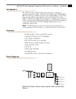
Page 3: ...ponent input Switches 3 through 8 set configuration features The exact function of each DIP switch and what it controls is described on the following pages Note Changing input format SW1 SW2 or SW3 causes a reset to occur that takes about 10 seconds to complete 5VDC Power Input Serial Digital Outputs 4 BNCs Composite Component Inputs Configuration determined by DIP switch on other side of Converter...

Page 4: ...t If SW 1 is ON YPbPr Input If SW1 is OFF or Y C S VIDEO If SW1 is ON ON OFF If set for COMPOSITE Input Pedestal is removed on inputs with 7 5 IRE Pedestal If set for COMPONENT Y Pb Pr Input Sets BETACAM levels If set for COMPOSITE Input For inputs without Pedestal If set for COMPONENT Y Pb Pr Sets SMPTE EBU N10 levels If set for COMPOSITE Input Pedestal is removed on inputs with 7 5 IRE Pedestal ...

Page 5: ...utput Disables test pattern output normal video operation Item Specification Serial Outputs SDI SMPTE 259M w EDH All outputs are separately buffered 4 x BNC Frequency Response Y 0 15db to 5 5 Mhz C 0 15db to 2 5 Mhz 2T K factor Less than 5 K Factor 2T Differential Gain 1 Differential Phase 1 degree A D Converters 10 bits 2X oversampling User Controls Selectable By External Dip Switch Input Video Fo...

Reviews: