6
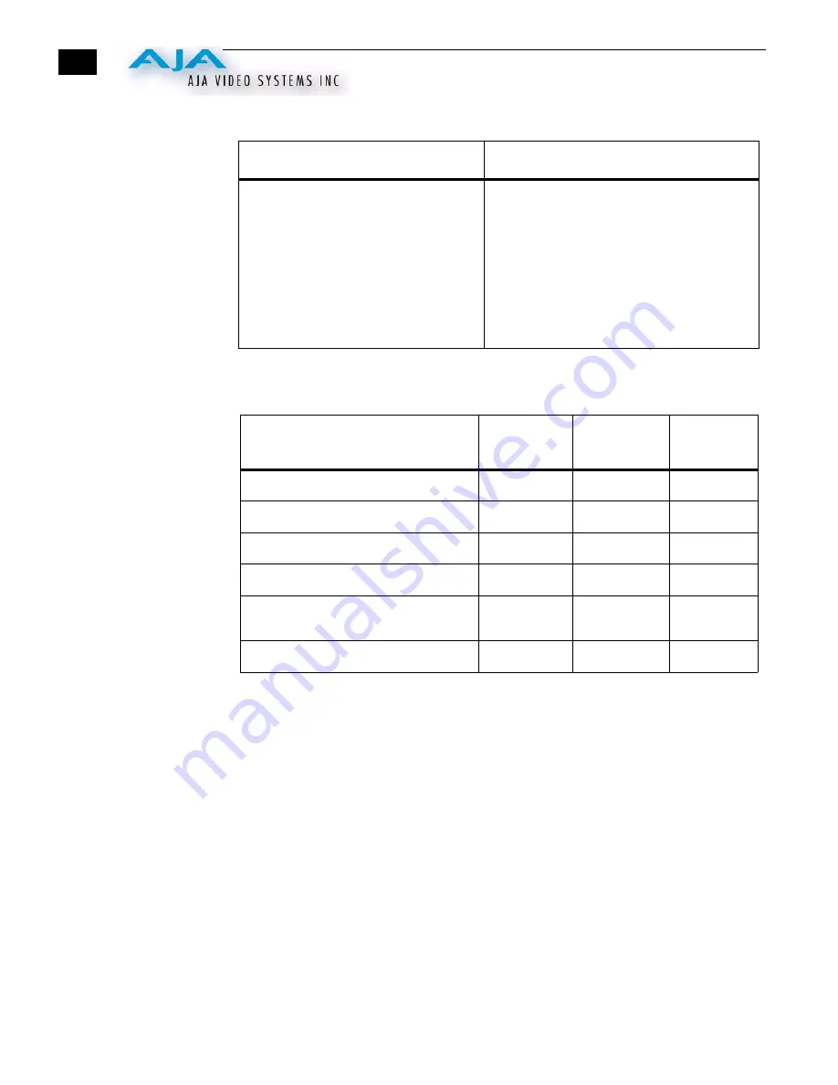
Switch 4 Configure Blanking For Component Output BNCs (3)
:
Output Selection
Matrix For Output
2 (3 BNCs)
The following table shows the combinations of DIP switch settings required to configure
the three BNCs below the COMPOSITE/SYNC BNC.
ON
OFF
WIDE Blanking:
Vertical—
Line numbers indicate where video
starts)
line 20, field 1; line 20, field 2 (525 line)
line 23, field 1; line 336, field 2 (625 line)
Horizontal—
Active video line duration
ITU-R/SMPTE (710 pixels NTSC,
702 pixels PAL)
NARROW (NAR) Blanking:
Vertical—
Line numbers indicate where video starts
line 13, field 1; line 12, field 2 (525 line)
line 10, field 1; line 322, field 2 (625 line)
Horizontal—
Active video line duration's)
ITU-R.470 (720 pixels PAUNTSC)~-
Output Format
DIP Switch
#1
DIP Switch
#2
DIP Switch
#3
1 Composite and 1 Y/C (Pedestal)
CMPSTE
N/A
ON
1 Composite and 1 Y/C (no pedestal)
CMPSTE
N/A
OFF
RGB
COMPNT
RGB
OFF
RGB with pedestal
COMPNT
RGB
ON
SMPTE component (BETA625)/
EBU-N10
COMPNT
YPbPr/YC OFF
BETA 525 component
COMPNT
YPbPr/YC
ON


