background image

FS1-X v1.1

www.aja.com

118


Figure 18. Typical GPI Input and Output Connections

Audio Connection Pinouts

Analog Audio

Figure 19. Analog Audio Connector Pinout

The two DB25 connectors on the FS1-X rear panel support a TASCAM-style cable snake 
for balanced 8-channel analog audio. The pinout is the same for both input and output 
connectors, each following the TASCAM DB-25 standard shown in the drawing above. 
The top connector is for analog audio inputs 1-8, and the bottom connector is for analog 
audio outputs 1-8

Digital Audio

Figure 20. Digital Audio Connector Pinout

1

15

11

5

6

10

GPI Out 4

GPI 

In 1

+V

xmit+

xmit-

Optical Relay (SSR)

To Tally Lamp etc.

GPI GND 4

GPI 

GND 1

G - + G - + G - + G - + G - + G - + G - + G - +

Analog

Audio

G = Ground     -/+ = Balanced Pair

Balanced

G

G

G

15/16

13/14

G

5/6

G

1/2

G

9/10 11/12

G

7/8

G

3/4

AES

Channels

G = Ground
To MUX into unbalanced AES BNC connections, use Balun 75 ohm adapter.

110 Ohm Balanced

 - +

 - +

 - +

 - +

 - +

 - +

 - +

 - +

Summary of Contents for FS1-X

Page 1: ...Installation Operation Guide Version 1 1 Published September 10 2014 FS1 X ...

Page 2: ...d Outputs 15 About Reference and Genlock Source 15 1 Channel vs 2 Channel FS1 X Operation 16 Sidebar Video Keying 16 Retained Settings 16 In This Manual 17 Chapter 2 Controls Indicators and Connections 18 Overview 18 Front Panel Description 18 Alphanumeric Display 18 Operational Summary 19 Pushbuttons 19 Control Knobs 21 LED Indicators 22 Incompatibility Alarms 23 Example Reference and Video Incom...

Page 3: ...o Level Choices Pro or Consumer US or EBU 35 Stand Alone Tests 37 First Power Up 37 Setup 37 Procedure 37 Internal Test Signals to All Outputs 38 Setup 38 Procedure 38 FS1 X Processing Examples 39 SD to Sidebar HD over Matte 39 Setup 39 Procedure 39 HD to Letterbox SD over Video 40 Setup 40 Procedure 40 Conversion Across Frame Rate Families 40 Setup 41 Procedure 41 Chapter 4 Display Menus 43 Overv...

Page 4: ...rs 55 5 Power Supply Alarm 55 6 1 Vid1 Format Alarm 55 6 2 Vid2 Format Alarm 55 7 Reference Alarm 56 8 Hidden Menus 56 9 Screen Saver 56 10 Display Intensity 56 11 Fan Speed 56 12 Serial Number 56 13 Software Version 56 14 Reboot 56 PRESET Menu Group 57 1 Factory Preset 57 1 1 1 40 Presets 1 40 57 Video with Audio Routing 57 Interaction of Presets and GPIs 58 SYSTEM Menu Group 58 1 Analog In Forma...

Page 5: ...rt Mode 67 8 Downconvert Mode 68 SD Aspect Ratio 69 9 SD Aspect Ratio Convert 69 Sidebars 70 10 Sidebar Edge 70 Matte of Background Fill 71 11 1 Matte Luma 71 11 2 Matte Chroma 71 11 3 Matte Hue 71 Proc Amp Controls YUV 71 12 0 Proc Amp YUV 71 12 1 Proc Amp Gain 71 12 2 Proc Amp Black 71 12 3 Proc Amp Hue 71 12 4 Proc Amp Sat 72 Color Corrector RGB 72 13 0 Color Corrector RGB 72 13 1 Color Red Gai...

Page 6: ...rn 79 Freeze Output 79 22 1Video 1 Freeze Output 79 22 2 Video 2 Freeze Output 79 Reverse Telecine 79 About Reverse Telecine and Film Cadence 3 2 and 2 3 3 2 79 FS1 X Reverse Telecine Conditions 80 23 Reverse Telecine 80 VIDEO OUTPUT Menu Group 80 1 1 SDI1 Video Out 80 1 2 SDI2 Video Out 80 2 1 Fiber1 Video Out 81 2 2 Fiber2 Video Out 81 3 HDMI Video Out 81 4 Analog 81 5 1 SDI1 3G Config 81 5 2 SD...

Page 7: ...0 Fiber1 Audio Out 88 4 0 Fiber2 Audio Out 88 5 0 AES EBU Audio Out 88 6 0 MADI BNC Audio Out 88 7 0 MADI Fiber Audio Out 88 8 0 HDMI Audio Out 89 9 0 Analog Audio Out 89 11 Global Output 89 12 Reset Mapped Output 89 Chapter 5 Browser Remote Control 90 Remote FS1 X Control Via a Web Browser 90 General Web Browser Screen Description 90 Controlling Multiple FS1 Xs 91 Resetting Values To Factory Sett...

Page 8: ... 4 3 SNMP Trap Destination 2 110 4 4 SNMP Trap Port 2 110 Appendix A Specifications 111 Video Input Output Formats 111 Video Format Conversion 112 Video A D D A Converters 115 Audio 115 Interfaces 116 Physical 116 Appendix B FS1 X Pinouts 117 GPI Pinouts 117 Audio Connection Pinouts 118 Analog Audio 118 Digital Audio 118 Appendix C Safety Compliance 120 Federal Communications Commission FCC Compli...

Page 9: ...FS1 X v1 1 www aja com 9 Warranty Information 129 Limited Warranty 129 Index 130 ...

Page 10: ...dia Interface are trademarks or registered trademarks of HDMI Licensing LLC DVI is a registered trademark of DDWG TASCAM is a registered trademark of TEAC Corporation Dolby and the double D symbol are registered trademarks of Dolby Laboratories All other trademarks are the property of their respective holders Copyright Copyright 2014 AJA Video Systems Inc All rights reserved All information in thi...

Page 11: ...s for broadcasters mobile trucks and production FS1 X supports both fiber and coax 64 channel MADI input and output An internal 224x224 audio matrix allows full routing of MADI and all audio coming from SDI fiber AES and analog sources for an incredible amount of audio processing capability in a single box FS1 X features a unique keyer configuration allowing incoming signals to be combined in powe...

Page 12: ...uts including embedded audio Other Features Built in front panel control via scrolling alphanumeric and graphical menu Front panel LED status indicators for at a glance system monitoring Linux operating system supporting full network compatibility including Web based remote control over 10 100 1000 Ethernet via an internal web server Two fully redundant power supplies standard Five year internatio...

Page 13: ...devices even getting them to identify themselves via LEDs on the front and rear panel GPI Inputs and Outputs General Purpose Inputs and Outputs are available on the FS1 X back panel to provide contact closure control Using the inputs an external contact closure activates a specified function on the FS1 X Using the outputs specific FS1 X functions can produce a contact closure to activate any desir...

Page 14: ...ts 4 Optional Fiber In 1 Optional Fiber In 2 SDI In 1 MADI BNC In SDI In 2 HDMI In Composite In AES EBU Digital Audio In 16 Channels Analog Audio In 8 Channels Tascam cable GPI Outputs 4 Optional Fiber Out 1 Optional Fiber Out 2 SDI Out 1 SDI Out 2 HDMI Out AES EBU Digital Audio Out 16 Channels Analog Audio Out 8 Channels Tascam cable Down Converter Composite Out Video Converter and Framesync Vide...

Page 15: ...left right stereo mix Operation Overview About Inputs and Outputs In general to use the FS1 X for video conversion first select an Output Video Format with the VIDEO PROC Output Format Menu that is compatible with the current FS1 X genlock source see About Reference and Genlock Source below then select an Input port on Video Processor 1 with the VIDEO PROC Video 1 Input menu The FS1 X will automat...

Page 16: ... Processor 2 video can be routed to the composite Video Output for downconversion The composite Video Output port has a separate dedicated Downconverter so it can always display SD video even if it is selected to output a Video Processor that is configured for HD Sidebar Video Keying The FS1 X can be configured to perform sidebar keying useful when converting between HD and SD with different image...

Page 17: ...x contents Chapter 2 Controls Indicators and Connections describes controls indicators and connections Chapter 3 Installation and Configuration provides complete instructions for installing and configuring the FS1 X Chapter 4 Display Menus explains how to use the FS1 X controls and display menus Chapter 5 Browser Control explains how to use the FS1 X remotely via a web browser on a network attache...

Page 18: ...th the groups one button per menu group The menu lines which are 23 characters wide display the following information First line parameter number and name Second line the editable value set for a parameter Third and fourth lines current status labels or prompts Figure 3 Four Lines of the Front Panel Display Activity Indicators VID In 1 2 UFC Proc Amp FRC Present FRC Active FMT ERR 1 2 Power and St...

Page 19: ...ry default Hold down ADJUST for 4 seconds Pushbuttons The general rules of Menu Group button operation are Press one of the nine Menu Group buttons to access the associated menu group The SELECT and ADJUST knobs control the display menus The selected Menu Group button lights and the other buttons turn off Each menu group returns to the last menu changed when you select the button After a reboot ea...

Page 20: ...ion Composite video downconvert settings HD to SD HDMI RGB Range AES audio input format and sample rate conversion settings VIDEO PROC Displays the Menu Groups that access Video Processor video input format and conversion selections and adjustments Settings for both Video Processor 1 and 2 Input source selections Loss of input selection H and V timing and delay settings Freeze output setting Input...

Page 21: ...DJUST Turning the ADJUST knob performs these actions Turn ADJUST to change the values of a selected parameter In most cases leaving a value in place for a moment sets that value To perform special actions such as recalling a register push the knob to confirm the displayed value Display line 4 indicates such special actions Some parameters having multiple fields such as IP Address require you to pu...

Page 22: ... blue Reserved for future use LAN blue The FS1 X is connected to an operational local area network This indicator lights momentarily when web browser selections are changed EXT blue flashing Flashes when a remote control source remote panel or GPI has initiated a change in the system PWR 1 2 blue Power Supply 1 or 2 is operational and receiving power Both PWR 1 and PWR 2 LEDs must be lit to indica...

Page 23: ... following examples Figure 4 Web page example of un supported signals alarm Table 2 Video Incompatibility Examples Video Incompatibility Detected Alarm Status screen will show Vid 1 Status screen will show Genlock Source is set to Reference but no Reference signal is detected In this example the cable has been disconnected IN1 SDI 1 OK BKGD Matte OK GEN Ref No Ref OUT1 1080i59 IN1 SDI 1 525i59 BKG...

Page 24: ... REMOTE menu group you can program the actions of the GPI inputs and outputs individually Contact closures on the inputs can trigger a wide variety of FS1 X functions Alarms or loss of video can trigger the GPI outputs 10 100 1000 LAN This RJ45 connector provides an Ethernet 10 100 1000 port for connection directly to a computer or to a LAN through an Ethernet hub or switch SDI Fiber In Out option...

Page 25: ...g video input connector cannot be used simultaneously You can choose either Component or Composite input but not both The same source video is also sent to both sets of analog video outputs Composite In Out Composite NTSC or PAL standard definition Input and Output Composite Video A D and D A converters are 12 bit Ref Loop The Reference Loop BNCs accept an Output timing reference signal The refere...

Page 26: ... mounting multiple FS1 X units try to place them visually in the same area so you can use an attached computer to turn on and see the ID LED of the FS1 X you re communicating with For physical installation details see FS1 X Chassis Installation on page 28 4 Connect the two FS1 X power cords to mains AC For redundancy use both power supplies and connect them to separate branch circuits so that the ...

Page 27: ...escription of the damage AJA will repair or replace damaged items If you find shipping damage contact your AJA dealer or distributor for details on how to have your FS1 X repaired or replaced NOTE Save packing materials and the shipping box If your FS1 X ever requires service or you move your system use the packaging materials and box for safe shipment Installing Optional Fiber Optic I O Modules T...

Page 28: ... cm Width 17 5 inches 44 45cm Weight 7 85 pounds 3 56 kilograms Cabling and Cooling Requirements Observe these precautions when placing your FS1 X Plan adequate space for cable routing from the back of the chassis Ensure that cable connectors are not stressed and cables are not bent or crimped When rack mounting or stacking multiple FS1 X chassis ensure adequate airspace for cooling around the FS1...

Page 29: ...ect the LAN to an outside wide area network WAN such as the internet Devices on a LAN have IP addresses which may be fixed and permanent or dynamically assigned by the network DHCP When attaching the FS1 X to a LAN talk to your network administrator to find out how they want it connected static IP or DHCP Your IT department will be able to supply the information you need to install the FS1 X on a ...

Page 30: ...1 Set your computer s IP address to whatever address you prefer 2 Set the computer s Subnet mask to 255 255 255 0 most PCs default to the proper netmask when the address is set 3 Set the gateway address if used to match the FS1 X default 192 168 0 1 Alternatively change the FS1 X gateway address to match your gateway A Press CONFIG turn SELECT to 2 4 Default Gateway push and then turn ADJUST to ch...

Page 31: ...momentarily to save the address 4 Turn SELECT to advance to 2 3 Subnet Mask Use the SELECT and ADJUST knobs as in the previous step to set the desired subnet mask 5 Turn SELECT to advance to 2 4 Default Gateway Use the SELECT and ADJUST knobs as in the previous step to set the desired gateway address 6 Run a browser on the computer and type in the IP address you set for the FS1 X You should now se...

Page 32: ...T again as needed to advance through the blinking octets 2 2 IP Address 192 168 0 2 Parameter Menu Current Setting Push ADJUST to edit octets Turn ADJUST to change values Push ADJUST to save Turn SELECT to scroll to parameter menu 2 3 Subnet Mask Turn SELECT again as needed to advance through the blinking octets 2 3 Subnet Mask 255 255 255 0 Parameter Menu Current Setting Push ADJUST to edit octet...

Page 33: ...solve the problem with your IT administrator Web Browser Control To control the FS1 X from a web browser on a network attached computer enter the FS1 X IP address as a URL in the browser For example if the FS1 X IP address were 90 0 6 31 you would then type into the web browser http 90 0 6 31 This topic is explained in greater detail in Chapter 5 Browser Remote Control NOTE The webUI browser GUI w...

Page 34: ... file For example FS1 X_ver_1 0 0 10 bin contained in the file downloaded from AJA 3 Click OK when asked if you want to Upload Firmware The file uploads to the FS1 X and is tested for validity Incomplete corrupted or non FS1 X files are rejected Wait for the procedure to complete it will take only a few minutes Progress bars show upload progress 4 Click Commit Uploaded Firmware when prompted after...

Page 35: ...ee GPI Pinouts on page 117 for information on how to wire the GPI connector to work with external devices that you want to use to control the FS1 X or that you want the FS1 X to control FS1 X Audio Level Choices Pro or Consumer US or EBU Since the FS1 X handles both digital and analog audio and can convert between the two it provides analog and digital audio level settings in the front panel menus...

Page 36: ...ital audio at the maximum possible level before clipping the expected analog audio input level is 18 dBu and the output is scaled to this level Typically the EU Alignment Level is 0dBu analog or 18 dBFS digital The FS1 X 18 dBu setting allows 18 dB of headroom 0 to 18 dBu per the EBU R68 standard 15 dBu analog 0 dBFS maximum audio level German standard With digital audio at the maximum possible le...

Page 37: ...y default the F1 X is configured to operate genlocked to an external reference signal 2 Press the front panel STATUS button then turn the SELECT knob to view various Status menus The Status menus will report No Input for the Video Processor video inputs the ports are disconnected and the GEN Genlock parameter will report Ref configured for external reference but will also report No Input or No Ref...

Page 38: ...f desired Internal Test Signals to All Outputs This workflow generates bars and tone and sends them to all the FS1 X outputs This example uses the HDMI output connector for convenient monitoring but any output can be used for that purpose In the following procedures where the terms select and adjust are used turn the front panel SELECT and ADJUST knobs Setup Connect the FS1 X HDMI output connector...

Page 39: ...s receiving a valid reference signal Connect a 525i59 94 SD SDI signal to the SDI1 input on the rear of the FS1 X Once connected the FS1 X front panel VID IN 1 LED will light Connect the FS1 X HDMI output connector to a compatible HDMI display Connect the FS1 X SDI1 video output connector to a compatible monitor NOTE The FS1 X factory default setting routes the output of Video Processor 1 to the S...

Page 40: ... Factory Preset Recall This recall sets the following default values for this procedure SYSTEM 1 1 Vid 1 Input is set to SDI 1 SYSTEM 1 2 Vid 2 Input is set to SDI 2 SYSTEM 3 Vid 1 Output Mode is set to Normal VIDEO OUTPUT 4 Analog is set to Vid 1 2 If the FRC option is present go to the SYSTEM menu Select 10 FRC Enable and adjust to Disable this sets 2 Channel mode This menu is not available on F...

Page 41: ...50 Hz adjust to Reference Otherwise select Free Run Select 9 Output Frame Rates and adjust to 50 25 Select 10 FRC Enable and adjust to Enable this sets 1 Channel mode The FRC ACTIVE LED will light blue because it is converting 59 94 Hz video to 50 Hz 2 Observe the monitor Motion will be completely smooth without momentary jumps or discontinuities and the FS1 X will not report any alarms To demonst...

Page 42: ...resent and Active with No Alarm This workflow confirms an FS1 X equipped with the FRC option can frame rate convert between frame rate families Vid 1 Format Status screen same Vid 1 Format Alarm Status screen IN1 SDI 1 1080i59 94 BKGD Black GEN Ref 1080i50 OUT1 1080i50 IN1 SDI 1 OK BKGD Black OK GEN Ref OK OUT1 1080i50 ...

Page 43: ...EO PROC Menu Group on page 63 VIDEO OUTPUT Menu Group on page 80 AUDIO PROC Menu Group on page 82 AUDIO OUTPUT Menu Group on page 87 Parameter Menus The FS1 X display presents five major types of menu pages Status pages present status information that cannot be changed Simple parameter menus contain a parameter number and name on line 1 and its current value setting on line 2 The line 2 value can ...

Page 44: ...re a group of related parameters Example 12 0 ProcAmp is the parent menu of the 12 1 through 12 4 child menus Menu Operation Examples The following examples demonstrate typical menu operation After this section each Menu Group is described in detail Status Pages These steps explain how to surf the STATUS menus 1 Press the STATUS Menu Group button 2 Turn the SELECT knob forward and backward to disp...

Page 45: ... ProcAmp 3 Turn the ADJUST knob to change the value setting from OFF default to ON 4 Turn the SELECT knob clockwise to access menu ProcAmp Gain and set the Gain as desired using the ADJUST knob 5 Turn the SELECT knob one click clockwise to advance to the ProcAmp Black menu Turn ADJUST to set the black level 6 Turn the SELECT knob clockwise again one click to advance to the ProcAmp Hue menu Turn AD...

Page 46: ...iod The field will blink when they are ready for editing 7 Turn the ADJUST knob to change the blinking field value For coarse adjustment of wide ranging values hold down CONFIG and turn ADJUST 8 Repeat this process of selecting fields and changing them until all fields have been changed as desired 9 Push the ADJUST knob quickly to confirm all settings Alternatively you can scroll counterclockwise ...

Page 47: ...press the STATUS button the display shows the first menu unless there is an active alarm If an alarm is active the relevant alarm status page is displayed first If more than one alarm is active the highest priority alarm page is displayed first Timing Delay Region of Interest Background Fill Custom Size Pos Downconvert Mode Proc Amp Color Corrector Video Input Output Format VIDEO PROC Menus Analog...

Page 48: ...ssor 2 selected video input and detected format Video Processor 2 video output format Display Description IN1 Input SourceFormat BKGD Backgd Source GEN Genlock SourceFormat OUT1 Format Selected Video Processor 1 video input source and format Selected Background video source Selected Genlock source and format Selected Video Processor 1 output format Display Description IN1 Input SourceStatus BKGD B...

Page 49: ...put Selected Processor feeding the Fiber 2 output Selected Processor feeding the HDMI output Selected Processor feeding the Analog output Display Description PS1 Alarm Status PS2 Alarm Status TmpAlarm Status Displays the state of the PS1 power supply OK or ERROR Displays the state of the PS 2 power supply OK or ERROR Displays a temperature alarm if the FS1 X overheats Display Description VID1CC Ca...

Page 50: ...X panel responds to controls locally from the front panel from a network attached computer with a web browser or both The selected mode is indicated by the color of the REMOTE LED 1 1 Authentication This parameter enables or disables an authentication login requirement By default this parameter is set to Disabled When you select Login via the front panel parameter you must then go to the browser i...

Page 51: ...s received at the FS1 X s GPI Inputs 1 4 A GPI Trigger is defined as a TTL low voltage level 0 to 0 8V with respect to its isolated ground pin The GPI interface pinout and specifications are Disabled default Login Disables the requirement for a login password No password is needed Login is required via the web browser interface before changes can be made in FS1 X After selecting Login depending on...

Page 52: ...eo input Selects Component In as the Vid1 video input Turns Off SD to SD aspect ratio conversion Converts 16 9 anamorphic video to letterbox Converts 16 9 anamorphic video to 4 3 standard H crop crops left and right edges of video Converts 4 3 standard video to 16 9 anamorphic pillarbox Converts letterbox video to 16 9 anamorphic V crop Converts 16 9 anamorphic video to 14 9 cropped Downconverts H...

Page 53: ... as desired before storing presets in the example set GPI IN 1 to Preset 1 before you store Preset 1 CONFIG Menu Group The CONFIG Menu Group includes parameters for setting up the FS1 X s network system name SNMP alarm and screen saver configurations 1 System Name This parameter defines a unique name for the FS1 X This same name is used both when displaying systems via the web interface and when d...

Page 54: ... gateway whether you have a router gateway or not the FS1 X will be unable to see other FS1 Xs on the network although you may still be able to control this FS1 X via a web browser Also without a proper gateway defined the discovery feature on the Network web page will fail to list other FS1 Xs on the network DHCP default Static Addr Select automatic IP address assignment from the LAN DHCP server ...

Page 55: ...m responds to power supply disconnection or failure If the FS1 X will be connected using only one power cord and supply you can suppress the alarm Changes to this setting are automatically saved 6 1 Vid1 Format Alarm When set to Normal default an alarm is triggered whenever the selected input video signal format of Video Proc 1 is incompatible with the selected output format refer to the matrix of...

Page 56: ...l cooling fans To prevent system damage this setting may be overridden temporarily and the fan can be set to a higher speed if the system detects very high internal temperatures Changes to this setting are automatically saved 12 Serial Number This parameter displays the FS1 X s unique serial number 13 Software Version This parameter displays the FS1 X s software version number 14 Reboot This param...

Page 57: ...hat match the desired audio inputs to each desired video input and use those presets to select the video inputs causing the configured audio to follow Caution When you recall a Preset Configuration the recalled preset immediately replaces the system s existing configuration All previous settings are lost unless you have previously stored them in another preset configuration or an exported file Fac...

Page 58: ... dBu to SMPTE professional 24 dBu NOTE See Chapter 3 FS1 X Audio Level Choices Pro or Consumer regarding audio levels 4 SDI1 3G Detect This parameter configures 3G operation of the SDI 1 video input SMPTE YPbPr default Beta YPbPr Composite Configure the Component Video Input source as SMPTE YPbPr This is the default for HD component video Configure the Component Video Input source as Beta YPbPr st...

Page 59: ...with SDI1 3G Detect above In the Normal setting default the SDI 2 video signal always comes from the SDI 2 physical input Choosing Auto Detect or Dual Stream in SDI1 3G Detect does not switch away from the physical input In the Dual Stream setting the FS1 X assumes both channels of Dual Stream 3G video are muxed onto a single wire at the SDI1 input The SDI 2 video signal is then taken internally f...

Page 60: ...at settings 10 FRC Enable This parameter Enables or Disables the factory installed Frame Rate Converter FRC option if present When present the FRC PRES LED on the FS1 X front panel will be ON Single Video signal 1080p 50 60 setting or Auto Detect with ANC 1080p data or Auto Detect with no ANC data Dual Stream SDI1 SDI1 SDI2 SDI2 Normal SDI1 SDI1 SDI2 SDI2 SDI 3G Detect Setting SDI2 Input Protect S...

Page 61: ...1 X does not convert NTSC to PAL M or vice versa 12 Composite Downconv This parameter selects the type of down conversion performed on the incoming selected HD source input for the analog composite NTSC or PAL video output NOTE Using the Downconverter adds a frame of video delay making the analog Composite output be one frame behind the other outputs 13 HDMI RGB Range This parameter selects the ou...

Page 62: ...h audio is rate converted and synced with video SRC is applied Bypass is available for use when Dolby 5 1 and similar schemes need to be preserved and the audio data passed unaltered no SRC is applied Set these parameters to Manual and Bypass only if BOTH the following items are true You want to pass unaltered digital encoded audio from either an embedded or AES Input to an embedded and or AES Out...

Page 63: ...r panel but the active input source routed to the selected Video Processor is the one you select here 1 1 Video 1 Input Source Memory Changing the Video Input selection automatically selects new values for Proc Amp parameters and Color Corrector RGB parameters Each video source remembers its own Proc Amp and Color Corrector settings This is referred to as Source Memory 64ch default 56ch Sixty four...

Page 64: ...nal video output of Video Processor 1 to normal video or the test pattern generator Alarms occur if conflicting video formats are selected NOTE Normal output for the Video Processor 1 can be a version of its currently selected input a Sidebar or Letterbox display a Freeze of last good video or Black depending on how the Video 1 process or has been configured Loss of Input This parameter selects th...

Page 65: ...l line width Adjustment range increments from 0 to the width of the line in pixels The maximum value varies depending on the format already chosen Table 6 Output Timing Ranges Output Frame Rate Horizontal Vertical Min Max Min Max 1080i50 0 2639 562 562 1080i59 94 1080i60 0 2199 562 562 1080p23 98 1080p24 0 2749 562 562 1080p25 0 2639 562 562 1080p29 97 1080p30 0 2199 562 562 1080p50 0 2639 562 562...

Page 66: ...e Sidebars 6 Background Fill Upconvert and Downconvert These parameters select the type of upconversion the Video Processor performs on the selected SD source input or the type of downconversion performed on the selected HD source input NOTE Any Custom Size Pos values will be applied on top of these Upconvert and Downconvert settings except when Downconvert Mode is set to AUTO AFD NOTE When conver...

Page 67: ...trations for examples 4x3 Pillar default 14x9 Pillar Full Screen LB to Full Wide Zoom Results in 4x3 image at center screen with black sidebars Results in 14x9 image zoomed slightly to fill a 14x9 image with black sidebars Anamorphic full screen display Image is zoomed to fit the full screen letterbox Using a combination of zoom and stretch the image is sized to fit a 16x9 screen this can introduc...

Page 68: ... area of the picture usually because it originally came from an Upconverted SD signal so the Downconverter Crop mode would be the best choice There are 16 possible HD AFD codes of which eight are in common use The FS1 X does not process or use SD AFD codes FS1 X AFD processing passing removing and re inserting occurs based on the setting of parameters 8 Downconvert Mode on page 68 12 Composite Dow...

Page 69: ...SD Aspect Ratio Convert 1 6 9 Downconvert Illustrations Anamorphic Letterbox 4 3 16 9 Downconverts To These displays on 4 3 Crop 14 9 Off default Letterbox H Crop Pillarbox V Crop 14 9 Turns aspect ratio conversion Off Converts 16 9 Anamorphic video to Letterbox video Converts 16 9 Anamorphic video to 4 3 Standard video crops left and right edges of video Converts 4 3 Standard video to 16 9 Anamor...

Page 70: ...maller equates to setting Left and Right Crop values to smaller percentages The Sidebar Edge can be set to 0 through 128 A value of 0 produces a 4 3 center Positive values produce wider sidebars and a narrower center 10 Sidebar Edge SD Aspect Ratio Conversion Illustrations H Crop Pillarbox V Crop 14 9 Off no conversion Letterbox 4 3 4 3 Converts To These displays on 4 3 0 default 0 to 128 Variable...

Page 71: ...rom 0 to 1 5 times luma in 0 01 steps 12 2 Proc Amp Black This parameter adjusts the video black level from 20 IRE to 20 IRE in 0 5 steps 12 3 Proc Amp Hue This parameter adjusts the video color hue through 360 degrees color wheel in 1 degree steps 50 default 0 100 Variable Sets the matte luminance level to the default 50 value Sets the matte luminance level from 0 100 50 default 0 100 Variable Se...

Page 72: ... Gamma for color Red Blue same as Color Red described above Custom Conversion Settings The custom settings determine the image size and shape for Upconvert and Downconvert modes if you choose the Custom selection for those modes Custom settings are stored separately for each Conversion Mode Values for each of the Upconvert modes Downconvert modes excluding AFD and SD Aspect Ratio modes excluding O...

Page 73: ...icture crop position 14 7 Custom Top Crop This parameter changes the Top picture crop position 14 8 Custom Bottom Crop This parameter changes the bottom picture crop position Off default On Sets this parameter and related custom size pos parameters to off Enables this parameter and related custom size position parameters 100 default 10 to 200 Maintains 100 picture size for the selected format Enab...

Page 74: ...of the Conversion Mode While downconverting with Downconvert Mode set to Auto AFD any values assigned for ROI parameters are ignored Custom Size and Position settings work interactively with ROI but Custom Crop settings are disabled Custom Size Pos is also temporarily disabled while in the ROI Setup mode 15 1 ROI Left This parameter sets the left boundary of the ROI 15 2 ROI Right This parameter s...

Page 75: ... level to the adjusted limit Limit can be set from 10 IRE to 20 IRE 16 3 Legalizer Chroma Clip When the Video Legalizer mode is YUV this parameter limits the maximum chroma level to the adjusted limit The limit can be set from 60 to 140 AFD These parameters determines if and where the Video Processor will insert a SMPTE 2016 Active Format Descriptor AFD packet into its output video The inserted AF...

Page 76: ...atio that is 16 9 Pillarbox The FS1 X always inserts a 4 3 center AFD code 9 which indicates that the HD image has a 4 3 aspect ratio as a horizontally center pillarbox image within the 16 9 frame Letterbox The FS1 X always inserts a 16 9 with complete 16 9 image protected AFD code 10 which indicates that the HD image is full frame with a 16 9 aspect ratio and all image areas are protected 14 9 Th...

Page 77: ...08 captioning The data formatting and encoding for 708 captions is very different from the data contained in 608 SD captioning reflecting the added features and capabilities available with the CEA 708 standard When the Caption Translator is on the FS1 X Upconverter automatically translates incoming line 21 captions to CEA 708 format and inserts the VANC packets into the converted HD video stream T...

Page 78: ...erted video 20 SD Line 21 Blanking Blank In Blank mode the FS1 X copies and remembers the contents of SD line 21 and then blanks those lines before transformation to ensure captioning data does not get included in the transformed video If the output video is SD 525i the copied caption information gets reinserted on line 21 of the output If the output video is Upconverted and parameter 18 Caption X...

Page 79: ...a way to convert film frame rates 24 fps to i59 94 interlaced field rate video suitable for broadcast commonly employed by telecine equipment when converting film to video This requires a 4 5 conversion ratio For 3 2 pulldown cadence the most common two fields are duplicated for every four input frames with a resulting Blank default In Upconvert or SD Aspect Ratio Convert modes this setting copies...

Page 80: ... X output format selected must be either p23 98 or PsF23 98 The Reverse Telecine parameter must be set to Auto Under the conditions above the FS1 X will automatically detect the type of film cadence 3 2 or 2 3 3 2 identify and remove the duplicate fields and perform motion detection and de interlacing processing to create high quality output with clean frames NOTE Approximately 10 incoming frames ...

Page 81: ...080p50 59 94 output In this case the SDI2 Video Out and SDI2 Audio Out selections are ignored 5 2 SDI2 3G Config The SDI2 3G Config parameter determines how 1080p50 59 94 signals are formatted for the SDI 2 output The two choices select either Level A or Level B as described in the SMPTE 425 standard If the SDI1 selection is Dual Link these SDI2 settings are ignored because the SDI 2 output is use...

Page 82: ...in to all the input channels When Adjust mode is selected After selecting an individual channel adjustment menu the ADJUST knob changes the value shown by 0 5 dB up or down for each knob detent The range of adjustment is 18 0dB to 18 0dB Switching from Unity to Adjust will apply the individual level values that were set in the Adjust mode to the input for each of the channels Switching from Adjust...

Page 83: ...g to will be applied when Global is selected When Channel Pair mode is selected Each of the individual eight SDI1 audio input channel pair delay values are applied to the input delay of each channel pair The range of delay is 128 to 12288 in units of samples where 48 samples 1 millisecond Switching from Global to Channel Pair will apply the individual delay values that were set for each individual...

Page 84: ... on page 82 2 0 SDI1 Phase on page 83 3 0 SDI1 Delay on page 83 10 0 11 0 12 0 Fiber2 Level Phase Delay See descriptions for SDI 1 1 0 SDI1 Level on page 82 2 0 SDI1 Phase on page 83 3 0 SDI1 Delay on page 83 13 0 14 0 15 0 AES Level Phase Delay See descriptions for SDI 1 1 0 SDI1 Level on page 82 2 0 SDI1 Phase on page 83 3 0 SDI1 Delay on page 83 16 0 17 0 18 0 MADI BNC Level Phase Delay Same co...

Page 85: ...els to the Left and Right outputs and adjust the gain of the Left and Right output channels About Mix Down Mode Multi channel audio uses more than two speakers to represent the sound field Figure 13 Multi Channel 5 1 and 7 1 Speaker Positions Multi channel audio typically embedded in an SDI or HDMI signal can be passed through the FS1 X converter unchanged The multi channel sound can also be mixed...

Page 86: ...o routing matrix 28 16 28 17 Mix Down 1 Output Lft Rt Level The level of the Left and Right mixer output signal can adjusted plus or minus 18 dB in half dB increments using these menu controls Default is 0 dB unity 29 0 Mix Down 2 Mode This menu and the following related parameter menus have the same controls as for Mix Down 1 Mode but apply to the Mix Down 2 processor See 28 0 Mix Down 1 Mode on ...

Page 87: ...channels are routed to the corresponding output channels For example SDI1 input Ch n to SDI1 output Ch n where n 1 thru 16 If the destination output has more channels than the source then mute silence is routed to the channel outputs beyond the source channel range Mix Down 1 Mix Down 2 Resets the Mix Down 1 mixer levels to default settings Resets the Mix Down 2 mixer levels to default settings On...

Page 88: ... Output Channel When Map is selected each listed source can be mapped to each output channel of the currently selected output menu 2 0 SDI2 Audio Out See 1 0 SDI1 Audio Out on page 87 3 0 Fiber1 Audio Out See 1 0 SDI1 Audio Out on page 87 4 0 Fiber2 Audio Out See 1 0 SDI1 Audio Out on page 87 5 0 AES EBU Audio Out See 1 0 SDI1 Audio Out on page 87 6 0MADIBNCAudio Out See 1 0 SDI1 Audio Out on page...

Page 89: ...g The selected source channels are routed to all the FS1 X output channels If the output has more channels than the source mute silence is routed to the higher numbered output channels If the output has fewer channels than the source the sources are routed to the lower numbered output channels Sig Gen 1KHz Sig Gen 400Hz Mute The selected tone or mute is routed to every FS1 X output channel Mix Dow...

Page 90: ...nnection For browser access enter the FS1 X IP address in the browser s address field By default the FS1 X is set to automatically connect to your network s DHCP server to get an IP address and other network configuration data You will find the IP address in the CONFIG Menu Group as follows 1 Press the CONFIG button on the FS1 X front panel 2 Turn the SELECT knob until you reach parameter IP Addre...

Page 91: ...e unit will blink to identify it Click on Identify again to stop the blinking Another way to identify systems is to notice which FS1 X system s EXT front panel LED flashes when you change any setting from a remote control device such as the web browser Figure 14 FS1 X Web Interface Main Status Screen ControllingMultiple FS1 Xs From any screen you can see at a glance all of the FS1 X devices presen...

Page 92: ... value The FS1 X will immediately operate with the new setting Slider Operation Some screens contain slider controls for setting values To set a value you can click on a slider to select it and then use the mouse to drag the slider to the position you desire For fine tuning while the slider is selected highlighted by a blue border use the keyboard left and right arrow keys to change the value one ...

Page 93: ...e or select Network from the Menu list on the left side of the screen to open the Network Configuration screen listing FS1 X network settings The Network Configuration screen allows you to view and change your FS1 X s network settings and then click Apply to activate them See Networking on page 29 for detailed setup instructions for connecting the FS1 X to a network Consult your network administra...

Page 94: ...ess assignment from the LAN DHCP server If the FS1 X cannot find a DHCP server it fails over to the static IP address Assign a static IP address manually using parameters 2 2 2 3 and 2 4 The factory default static IP address 192 168 0 2 Variable If IP Address Type is set to DHCP the IP address is set automatically by the network DHCP server and cannot be entered here If IP Address Type is set to S...

Page 95: ...To close the window press the ESC key or click the X in the upper right corner The Alarm Configuration display provides control over these alarm settings Power Supply Alarm see 5 Power Supply Alarm on page 55 Video 1 and Video 2 Format Alarm see 6 1 Vid1 Format Alarm on page 55 Reference Alarm see 7 Reference Alarm on page 56 FS1 X Alarms display button gear icon Alarm Configuration popup display ...

Page 96: ...sion AFD and ROI are On or Off Shows the source and format of Background video Video 2 INPUT OUTPUT Caption Translator Shows the input source and format for Video Processor 2 Shows the output video selection and format for Video Proc 2 Shows the captioning selection and signal presence Video Output SDI 1 SDI 2 Fiber 1 Fiber 2 HDMI Composite Component Shows which processor is feeding the SDI 1 outp...

Page 97: ...ts Audio Output Global Audio Output Right clicking on the Global Audio Out parameter lets you select a global output That same audio will be sent to all the FS1 X audio outputs When set to Off the other Audio Outputs display their selected value otherwise only the Global Audio Output setting is displayed SDI 1 SDI 2 Fiber 1 Fiber 2 HDMI MADI MADI Fiber AES Analog Each of these settings when visibl...

Page 98: ...n page 60 7 Fiber2 Input Protect on page 60 8 Genlock Source on page 60 9 Output Frame Rates on page 60 10 FRC Enable on page 60 11 NTSC Standard on page 61 12 Composite Downconv on page 61 13 HDMI RGB Range on page 61 14 0 AES EBU SRC Mode on page 62 15 1 MADI BNC Out on page 63 15 1 MADI Fiber Out on page 63 Config Screen The Config screen includes functions to name the FS1 X configure SNMP hide...

Page 99: ...t UPnP Host enables the FS1 X to be discovered by a Windows network When this parameter is enabled you can view the FS1 X on a Windows Network by clicking these selections in Windows 7 Start Computer Network in left pane Any FS1 Xs on the network will be listed under Other Devices below Computers and Media Devices If your system does not have network discovery enabled you may need to enable it fol...

Page 100: ...to save FS1 X Preset Configurations into 40 separate memory registers and recall the presets whenever needed This screen also includes Export and Import functions that allow exporting one or all FS1 X presets to your computer as files and importing exported preset files from your computer A displayed message indicates successful or failed saves recalls exports and imports Presets Screen Controls F...

Page 101: ...ster associated with the selected button A dialog box warns you that the operation will overwrite the current preset contents with the file contents Export Presets 1 40 All Export All lets you save the contents of all presets to a file on your computer The file gets exported to the default download location specified in your browser options with the name all presets If you export multiple files a ...

Page 102: ...f control knobs Complete descriptions of these parameters are accessible using the following cross references 1 1 Video 1 Input on page 63 1 2 Video 2 Input on page 64 2 Output Format on page 64 3 Video 1 Output Mode on page 64 Loss of Input on page 64 Timing and Delay on page 65 6 Background Fill on page 66 7 Upconvert Mode on page 67 8 Downconvert Mode on page 68 9 SD Aspect Ratio Convert on pag...

Page 103: ...l connectors The parameters available on the Video Output browser screen are identical to the front panel display menus Complete descriptions of these parameters are accessible using the following cross references 1 1 SDI1 Video Out on page 80 1 2 SDI2 Video Out on page 80 2 1 Fiber1 Video Out on page 81 2 2 Fiber2 Video Out on page 81 3 HDMI Video Out on page 81 4 Analog on page 81 5 1 SDI1 3G Co...

Page 104: ...and brings up individual sub menu controls to allow making changes to those settings The sub menus are a lighter gray color and have a collapse expand button on the parent selection This lets you collapse the sub menus to make it easier to navigate the menu while configuring the system The collapsed setting only stays in effect until the user reconnects or refreshes the browser Descriptions of the...

Page 105: ...s were previously set for that item and brings up individual sub menu controls to allow making changes to those settings The sub menus are a lighter gray color and have a collapse expand button on the parent selection This lets you collapse the sub menus to make it easier to navigate the menu while configuring the system The collapsed setting only stays in effect until the user reconnects or refre...

Page 106: ...outputs NOTE The Remote Menu Group parameters available on the front panel interact with the browser parameters available on an attached computer and vice versa For example the Remote Control parameter can only be changed from the front panel and when set to Local Only will deactivate all browser remote control parameters See REMOTE Menu Group on page 50 for detailed information about FS1 X remote...

Page 107: ...tware The following page provides FS1 X support information and will include links to locations where you can download updates http www aja com en products FS1 X support After downloading the software update to your local drive use the Browse button to locate the local software copy Follow the prompts to load the new firmware into the FS1 X See Software Update Installation on page 33 for more info...

Page 108: ...be defined with fixed IP addresses When SNMP is enabled one or more of these alarms may be sent by the FS1 X to the client network management system NMS as a trap message FS1 XPowerSupplyAlarm PS1 Alarm FS1 X PowerSupply2Alarm PS2 Alarm FS1 XReferenceAlarm Ref Video Alarm FS1 XVid1ReferenceAlarm Vid1 Ref Video Alarm FS1 XVid2ReferenceAlarm Vid2 Ref Video Alarm FS1 XVid1FormatAlarm Vid1 Format Alar...

Page 109: ... octet you want to edit indicated by blinking 3 Turn ADJUST to enter the new value If you need to revert to the previous setting undo changes push SELECT 4 Push ADJUST momentarily to save and activate the new setting If you want to revert to the default value hold down ADJUST for 4 seconds Web Browser SNMP direct configuration settings are available on the Config screen of the web browser interfac...

Page 110: ...e parameter the port changes immediately to the new value 4 3 SNMP Trap Destination 2 This parameter determines the secondary SNMP Trap Destination IP address where trap messages issued by the FS1 X will be sent if desired This parameter is similar to 4 1 SNMP Trap Destination 1 above The default is 192 168 0 3 4 4 SNMP Trap Port 2 This parameter determines the SNMP Trap Port used for sending dest...

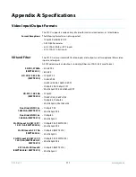
Page 111: ...SD SDI 270Mb SMPTE 259 C 525i 59 94 625i 50 HD SDI 1 4835 Gb SMPTE 292 720p 59 94 1080i 59 94 1080PsF 23 98 1080PsF 29 97 1080p 23 98 1080p 29 97 2Kx1080p 23 98 2Kx1080p 29 97 HD SDI 1 485 Gb SMPTE 292 720p 50 1080PsF 24 1080PsF 25 1080p 24 1080p 25 2Kx1080p 24 2Kx1080p 25 Dual link HD SDI 2x 1 4835Gb SMPTE 372 1080p 59 94 2Kx1080p 59 94 Dual link HD SDI 2x 1 485Gb SMPTE 372 1080p 50 2Kx1080p 50 3...

Page 112: ... 50 720p 50 59 94 1080i 59 94 1080PsF 23 98 24 25 29 97 1080p 23 98 24 25 29 97 Composite SD Analog The FS1 X composite analog video input output formats are listed below If the component inputs are used the composite input is not available 525i 59 94 switchable to NTSC 7 5 IRE or 0 IRE setup 625i 50 Reference 525i 59 94 625i 50 analog composite 720p 50 59 94 tri level sync 1080i 50 59 94 tri leve...

Page 113: ...pported Conversions FRC Enabled Input Format Output Format Genlock Formats supported 1080i50 1080PsF2398 1080p2398 2K1080p2398 525i5994 720p5994 1080i5994 1080p2398 1080PsF2398 1080i5994 1080p24 1080p50 1080p5994 1080PsF24 1080p25 1080p2997 1080PsF25 1080PsF2997 525i5994 625i50 720p50 720p5994 1080i50 1080PsF24 1080p24 2K1080p24 1080p24 1080PsF24 1080i5994 1080p2398 1080p50 1080p5994 1080PsF2398 1...

Page 114: ...50 1080PsF2997 1080p2997 2K1080p2997 525i5994 720p5994 1080i5994 1080p2398 1080p24 1080p25 1080p50 1080PsF2398 1080PsF24 1080PsF25 625i50 720p50 1080i50 525i5994 720p5994 1080i5994 1080p5994 2K1080p5994 525i5994 720p5994 1080i5994 1080p2398 1080p24 1080p50 1080p25 1080p2997 1080PsF25 1080PsF2997 1080PsF2398 1080PsF24 625i50 720p50 Table 7 Supported Conversions FRC Enabled continued ...

Page 115: ...alanced analog I O DB 25F 25 pin connector Tascam pinout 16 channel AES EBU I O BNC DB 25F 25 pin connector 16 channel SDI HD SDI embedded BNC 2 16 channel SDI HD SDI embedded Fiber 2 64 channels MADI digital audio BNC 64 channels MADI digital audio Fiber Analog Audio Levels Analog audio input and output levels as referenced to full scale digital can be set to 12dBu consumer 15dBu 18dBu 24dBu prof...

Page 116: ...cifications Physical Dimensions Width 17 5 inches 44 45cm 19 inches 48 26 cm including rack ears Depth 16 inches 40 65 cm including knobs and connectors that extend beyond the frame Height 1RU 1 75 inches 4 44cm Weight 7 85 pounds 3 56 kilograms Temperature Operating temperature range 0 40 degrees C Cooled via two internal fans and side vents Power Voltage 100 240 VAC Power Consumption 55 Watts 60...

Page 117: ...olated 5V supply so that a relay contact closure or any device sinking at least 0 4 mA to ground will register a logic low All four GPI outputs are 5V TTL compatible sourcing up to 6mA and sinking up to 4mA each GPI Inputs light the front panel EXT LED when triggered The following illustration shows typical external wiring to the GPI connector The GPI inputs require some kind of contact closure be...

Page 118: ...lowing the TASCAM DB 25 standard shown in the drawing above The top connector is for analog audio inputs 1 8 and the bottom connector is for analog audio outputs 1 8 Digital Audio Figure 20 Digital Audio Connector Pinout 1 15 11 5 6 10 GPI Out 4 GPI In 1 V xmit xmit Optical Relay SSR To Tally Lamp etc GPI GND 4 GPI GND 1 G G G G G G G G Analog Audio G Ground Balanced Pair Balanced G G G 15 16 13 1...

Page 119: ... is used for the AES EBU digital audio connections except each channel handles a pair of digital audio signals 16 total per connector The top connector is for digital audio input channels 1 16 and the bottom connector is for digital audio output channels 1 16 ...

Page 120: ... equipment and receiver Connect the equipment into an outlet on a circuit different from that to which the receiver is connected Consult the dealer or an experienced radio TV technician for help FCC Caution This device complies with Part 15 of the FCC Rules Operation is subject to the following two conditions 1 This device may not cause harmful interference and 2 this device must accept any interf...

Page 121: ...R9 12 CSA C22 2 NO 60065 2003 A1 06 A2 12 GS EN 60065 2002 A1 2006 A11 2008 A2 2010 A12 2011 Additional licenses issued for specific countries available on request Emissions EN 55103 1 2009 EN 61000 3 2 2009 04 EN 61000 3 3 2008 06 Immunity EN 55103 2 2009 EN 61000 4 2 2008 12 EN 61000 4 3 2010 04 EN 61000 4 4 2011 03 EN 61000 4 5 2005 11 EN 61000 4 6 2008 10 EN 61000 4 11 2004 03 The product is a...

Page 122: ...t must not be disposed of with your other household waste Instead it is your responsibility to dispose of your waste equipment by handing it over to a designated collection point for the recycling of waste electrical and electronic equipment The separate collection and recycling of your waste equipment at the time of disposal will help conserve natural resources and ensure that it is recycled in a...

Page 123: ...reil près de l eau et nettoyez le seulement avec un tissu sec Warnung Das Gerät nicht in der Nähe von Wasser verwenden und nur mit einem trockenen Tuch säubern Advertencia No utilice este dispositivo cerca del agua y límpielo solamente con un paño seco Aviso Não utilize este dispositivo perto da água e limpe o somente com um pano seco Avviso Non utilizzare questo dispositivo vicino all acqua e pul...

Page 124: ...agés que du liquide a été versé ou des objets sont tombés dans l appareil que l appareil a été exposé à la pluie ou à l humidité ne fonctionne pas normalement ou est tombé Warnung Das Gerät sollte nur von qualifizierten Fachkräften gewartet werden Eine Wartung ist fällig wenn das Gerät in irgendeiner Weise beschädigt wurde wie bei beschädigtem Netzkabel oder Netzstecker falls Flüssigkeiten oder Ob...

Page 125: ...es blessures dues à un choc électrique Warnung Hochspannung Diese Situation oder Bedingung kann zu Verletzungen durch Stromschlag führen Advertencia Alto voltaje Esta situación o condición puede causar lesiones debidas a una descarga eléctrica Aviso Alta Tensão Esta situação ou condição pode causar danos devido a choques elétricos Avviso Alta tensione Questa situazione o condizione può causare les...

Page 126: ...gung gestellte Stecker nicht in Ihren Anschluss passt konsultieren Sie einen Elektriker um den veralteten Anschluss zu ersetzen Advertencia No eche por tierra la finalidad del tipo de enchufe polarizado con conexión a tierra Un enchufe polarizado tiene dos espigas una más ancha que la otra Un enchufe con conexión a tierra tiene dos espigas iguales y una tercera espiga que sirve para la conexión a ...

Page 127: ...meiden Sie dass auf das Netzkabel getreten oder das Kabel geknickt wird insbesondere an den Steckern den Steckdosen und am Kabelausgang am Gerät Advertencia Proteja el cable de energía para que no se le pise ni apriete en especial cerca del enchufe los receptáculos de conveniencia y el punto del que salen del equipo Aviso Proteja o cabo de alimentação de ser pisado ou de ser comprimido particularm...

Page 128: ...permita manutenção pelo usuário Abrir o chassi anula a garantia a menos que a abertura seja realizada por uma central de serviços da AJA ou por um local autorizado Avvertenza Non aprire lo chassis All interno non ci sono parti riparabili dall utente L apertura dello chassis invaliderà la garanzia se non viene effettuata da un centro ufficiale o autorizzato AJA Warning To meet safety regulations fo...

Page 129: ...duties taxes and any other charges for products returned to any other locations This warranty shall not apply to any defect failure or damage caused by improper use or improper or inadequate maintenance and care AJA Video shall not be obligated to furnish service under this warranty a to repair damage resulting from attempts by personnel other than AJA Video representatives to install repair or se...

Page 130: ...nu 58 Analog Audio Connectors 24 Analog Audio Pinouts 118 Analog In Format Menu 58 Analog Video 58 Applications Typical 12 Audio Audio Proc 1 and Audio Proc 2 Menu Groups 104 Connections pinout 118 Features 12 Global Output Menu 89 Inputs and Outputs Specifications 115 Level Choices 35 Phantom Power 35 Reset Mapped Output Menu 89 Audio and Video Routing Using Presets 57 Audio Connectors Analog 24 ...

Page 131: ...ay 18 Conversion Procedure 15 Conversion Exceptions 111 Cooling Requirements 28 Custom Custom Aspect Menu 73 Custom Bottom Crop Menu 73 Custom H Position Menu 73 Custom Left Crop Menu 73 Custom Right Crop Menu 73 Custom Size Menu 73 Custom Size Pos Menu 72 Custom V Position Menu 73 D Default Gateway Menu 54 Depth 28 Description Technical 14 Digital Audio Pinouts 118 Dimensions Chassis 28 Display A...

Page 132: ...4 GPI Inputs and Outputs 13 GPIs GPI 1 4 OUT Menu 53 GPI Connections 35 GPI Connections pinout 117 GPI I O Specifications 116 GPI IN 1 4 Response Menu 51 GPI Typical Connections 117 Interactions with Presets 53 H HD to Letterbox SD over Video 40 HDMI HDMI RGB Range 61 HDMI Video Input Specifications 112 HDMI Video Out Menu 81 HDMI In Out Connectors 25 Height 28 Hidden Menus 56 Hidden Parameter Men...

Page 133: ...3 Custom Left Crop 73 Custom Right Crop 73 Custom Size 73 Custom Size Pos 72 Custom V Position 73 Default Gateway 54 94 Display Intensity 56 Downconvert AFD Default 77 Downconvert Mode 68 Embedded Audio Out 87 Factory Preset 57 Fiber1 1080p50 60 Config 82 Fiber1 Video Out 81 Fiber1 3G Detect 60 Fiber2 1080p Config 82 Fiber2 Input Protect 60 Fiber2 Video Out 81 Frame Delay 66 Frame Rate 60 FRC Enab...

Page 134: ... Freeze Output 79 Video 2 Input 64 Video 2 Input Scan 78 Video Input 63 Video Legalizer 75 Video Output Mode 64 Menus Parameter 43 Mix Down Input Level Menu 86 Mix Down Input Mapping Menu 86 Mix Down Input Menu 86 Mix Down Mode description 85 Mix Down Mode Menu 85 Mix Down Output Level Menu 86 Multi Channel 5 1 Mixdown Default 85 Multi Channel 7 1 Mixdown Default 85 Multi Channel Speaker Positions...

Page 135: ...72 Proxy UPnP 100 Pushbuttons 19 PWR 1 2 LEDs 22 R Rear Panel Description 24 Reboot Menu 56 Recall Presets browser screen 101 Recall 91 1 101 Redundant Power Supplies 26 Ref Loop Connectors 25 Reference Overview 15 Ref Connector 22 Ref LED 22 Reference Alarm Menu 56 Termination 25 Video Reference Specifications 112 Region of Interest 74 Region of Interest Menu 74 Remote browser screen 106 Remote B...

Page 136: ... 112 Video Input Output 111 Stand Alone Tests 37 Status Caption Status 49 FRC Status 49 I O 48 MADI Status 49 Output Status 49 Power Temp Alarm Status 49 Status Button 19 47 Status Menu Group 19 47 STATUS Menus 44 System Status 50 Vid 1 Format Alarm Status 48 Vid 2 Format Alarm Status 48 Vid 2 Format Status 48 Vid1 Format 48 Status browser screen 96 Store Presets browser screen 101 Subnet Mask 94 ...

Page 137: ...o 1 Test Pattern Menu 79 Video 2 Freeze Output Menu 79 Video 2 Input Menu 64 Video 2 Input Scan Format Menu 78 Video Conversion Procedure 15 Video Format Alarms 115 Video Output Video Output Button 20 Video Output Menu Group 20 Video Output browser screen 103 Video Proc Video Proc Button 20 Video Proc Menu Group 20 Video Proc browser screen 102 Video Processor Technical Description 15 Video Proces...

Reviews: