background image

www.aja.com

49


FS4 Frame Synchronizer/Converter v1.1

Vid Alarm

(Single Ch only) This menu shows the Video Processor 1 alarm status. Absence of alarm 
shows as 

OK

. If selections are incompatible, the status of the affected signal shows 

Incompat

SDI Input

This menu shows the status of all eight SDI inputs.

Monitor Output

This menu shows the status of the monitor outputs (BNC and HDMI). 

AES Input

This menu shows the status of all eight AES channel pair inputs. Each can carry a stereo 
digital audio signal.

MADI In/Out

This menu shows the status of the MADI audio inputs and outputs. 

Power/Temp Alarm

This menu shows the power supply status of the FS4 and the temperature status. If a 
power supply is unplugged, the display indicates 

PS OFF

 or 

PS Error

.

Display

Description

IN

Input Source(s)

Status

GEN

Genlock Source

Status

Rate

Status

Video input source alarm status.
Selected Genlock source alarm status.
System Output Frame Rate (59/29/23.98, 50/25, 60/30/24)

Display

Description

SDI1

Status

SDI5

Status

SDI2

Status

SDI6

Status

SDI3

Status

SDI7

Status

SDI4

Status

SDI8

Status

Statuses for SDI inputs 1-8: (Format, No Input, No SFP)

Display

Description

Monit

Status

Fmt

Status

Crop

Status

Output selected for monitoring (Vid1-4 Out)
Output format.
Crop status (Off, On).

Display

Description

AES1

Status

AES5

Status

AES2

Status

AES6

Status

AES3

Status

AES7

Status

AES4

Status

AES8

Status

Statuses for AES inputs 1-8: (Present, No Input)

Display

Description

BNC In

Mode

Status

BNC Out Mode
Fib In

Mode

Status

Fib Out

Mode

BNC input mode (56ch, 64ch), status (Present, No Input)
BNC output mode
Fiber input mode, status
Fiber output mode.

Display

Description

PS1 Alarm

Status

PS2 Alarm

Status

TmpAlarm

Status

Displays the state of the PS1 power supply (OK or ERROR).
Displays the state of the PS 2 power supply (OK or ERROR).
Displays a temperature alarm if the FS4 overheats.

Summary of Contents for FS4

Page 1: ...Installation Operation Guide Version 1 1 Published August 31 2016 FS4 ...

Page 2: ...tion Overview 16 About Inputs and Outputs 16 About Reference and Genlock Source 16 Retained Settings 17 In This Manual 17 Chapter 2 Controls Indicators and Connections 18 Overview 18 Front Panel Description 18 Front Panel Layout and Operation 18 Operational Summary 19 Multiple Part Parameter Editing 19 Coarse Adjust Editing 19 Undo a Change 19 Reset to Factory Default 19 Alphanumeric Display 19 St...

Page 3: ...date Installation 32 Download the Latest Software 32 Unpack the Software 32 Uploading and Installing the Software to the FS4 32 System Cabling 33 System Video Audio Cable Connections 33 Four Channel Mode Configuration Examples 33 Four Channel Mode Input Examples 34 Four Channel Mode Output Examples 36 Four Channel Mode Conversion Examples 38 Single Channel Mode Configuration Examples 39 Single Cha...

Page 4: ... 3G Detect 54 4 2 SDI2 Input Protect 54 4 3 4 5 4 7 SDI3 5 7 3G Detect 55 4 4 4 6 4 8 SDI4 6 8 Input Protect 55 5 1 VidProc Bypass 55 CONFIG Menu Group 55 1 System Name 55 Name Entry Procedure 56 2 FS4 Mode 56 3 1 IP Config 56 3 2 IP Address 56 Octet Value Entry Procedure 56 3 3 Subnet Mask 57 3 4 Default Gateway 57 3 5 MAC Address view only 57 4 SNMP Enable Parameters 57 About FS4 Alarms 57 5 1 5...

Page 5: ... Reverse Telecine 66 About Reverse Telecine and Film Cadence 66 FS4 Reverse Telecine Conditions 66 4 Input Scan Format 67 ANC Menu Group 68 1 1 AFD Out 68 1 2 AFD VANC Output Lines 68 1 3 Downconvert AFD dflt 69 2 Caption Xlator 69 3 SD Line 21 Blanking 70 COLOR Menu Group 70 1 0 Proc Amp Enable YUV 70 1 1 Proc Amp Gain 70 1 2 Proc Amp Black 71 1 3 Proc Amp Hue 71 1 4 Proc Amp Sat 71 2 0 Color Cor...

Page 6: ...1 Background Fill 80 2 Sidebar Edge 80 11 1 Matte Luma 80 11 2 Matte Chroma 80 11 3 Matte Hue 80 TIMING Menu Group 80 1 Output Timing H 81 2 Output Timing V 81 3 Frame Delay 82 TSTGEN Menu Group 82 1 Test Pattern Gen 82 2 Test Pattern 83 FREEZE Menu Group 83 1 Freeze Output 83 Audio Select Buttons EMBED AES 83 LEVEL Menu Group 83 EMBED Level Menus 84 1 0 SDI1 Level 84 1 1 1 16 SDI1 Level Ch 1 84 2...

Page 7: ...etwork Configuration Screen 91 IP Address Type 91 IP Address 92 Netmask 92 Default Gateway 92 Alarm Configuration Screen 93 Status Screen 94 Config Screen 96 System Name 96 FS4 Mode 96 SNMP Parameters 97 Hidden Menus 97 Screen Saver 97 Display Intensity 97 Fan Speed 97 UPnP Host 97 UPnP Proxy 97 Video Screen 98 Audio Screen 99 Presets Screen 100 Presets Screen Controls 100 Factory Preset 100 Recal...

Page 8: ... Configuration Parameters 115 4 0 SNMP Enable 115 4 1 SNMP Trap Destination 1 115 4 2 SNMP Trap Port 1 115 4 3 SNMP Trap Destination 2 115 4 4 SNMP Trap Port 2 115 Appendix A FS4 Specifications 116 Modes of Operation 116 Video Formats 116 Video Input Digital 116 Video Output Digital 116 Monitor Output Digital 117 Video Processing 117 Format Conversion 118 Scaling 118 Up Conversion 118 Down Convers...

Page 9: ... Canadian ICES Statement 124 European Union and European Free Trade Association EFTA Regulatory Compliance 125 Declaration of Conformity 125 Recycling Notice 126 Korean KCC Compliance Statement 126 Taiwan Compliance Statement 126 Japanese Compliance Statement 126 Translated Warning and Caution Messages 127 Before Operation Please Read These Instructions 127 Warranty Information 135 Limited Warrant...

Page 10: ...United States and or other countries HDMI the HDMI logo and High Definition Multimedia Interface are trademarks or registered trademarks of HDMI Licensing LLC DVI is a registered trademark of DDWG TASCAM is a registered trademark of TEAC Corporation Dolby and the double D Dolby logo are registered trademarks of Dolby Laboratories Licensing Corporation openGear Ross ROSS ROSS and MLE are registered...

Page 11: ... The growth of 5 1 and 7 1 audio has increased the number of audio channels that must be managed in a production as well as needing to create stereo mixdowns from 5 1 and 7 1 sources The MADI standard provides a convenient way to transport large numbers of audio channels along a single cable simplifying the cabling demands for broadcasters mobile trucks and production FS4 supports both fiber and c...

Page 12: ...5 1 and 7 1 to Stereo mixdown processors Other Features Simple operation redesigned menu structure and quick access to features via front panel buttons or web UI Built in web server Supports remote status and control and remote software updates Presets Redundant power Configurable Alarms EIA 19 Rack mountable 1RU frame offering space power and cost efficiencies ideal for outdoor broadcast trucks p...

Page 13: ...xible architecture offering powerful Video Processors for video conversion and processing a separate Audio Processor and input and output video and audio signal routing The FS4 has two completely separate operating modes selected with a menu parameter and then rebooting the unit Four Channel Mode In Four Channel Mode four independent HD SD Video Processors are available Frame synchronization genlo...

Page 14: ...K UltraHD FS4 CPU Inputs Passive Reference Loop Embedded Web Server Panel Control GPI Inputs 4 GPI Outputs 4 SDI In 3 MADI BNC In SDI In 4 SDI In 1 SDI In 2 Video Monitor HDMI Out Video Monitor SDI Out Video Converter and Frame Sync Video Proc Amp and Color Corrector Remote Web Browser Control SNMP Control via Command Line Genlock Outputs Processing HD SD VIDEO PROCESSOR 1 HD SD VIDEO PROCESSOR 2 ...

Page 15: ...tment with standard Proc Amp controls and RGB style color correction FS4 CPU Inputs Passive Reference Loop Embedded Web Server Panel Control GPI Inputs 4 GPI Outputs 4 SDI In 3 MADI BNC In SDI In 4 SDI In 1 SDI In 2 Video Monitor HDMI Out Video Monitor SDI Out Video Converter and Frame Sync Video Proc Amp and Color Corrector Remote Web Browser Control SNMP Control via Command Line Genlock Outputs ...

Page 16: ...through 8 In and Out also support 12G and 6G SDI when equipped with a compatible SFP module The FS4 supports optional AJA Optical SFP I O modules as follows Single Input LC connector up to 3G Single Input SC connector up to 3G Single Output LC connector up to 3G Single Output SC connector up to 3G Dual Input LC connectors up to 12G Dual Output LC connectors up to 12G Dual CWDM Dual HD BNC connecto...

Page 17: ...ally selects new values for H V timing parameters This is referred to as Output Timing Memory Each Output Format mode remembers its own H V timing settings As another example Output Format Mapping stores the Output Format selected for any of the frame rates That Mapped Output Format is recalled if the frame rate selection is changed Presets can also be used to restore the FS4 to a previous state M...

Page 18: ... reconfiguration When a System Selection button is pressed the parameter menu that was last selected from that group will be displayed Pressing any of these buttons de selects all other SYSTEM buttons CHANNEL SELECT buttons VIDEO menu group buttons and AUDIO menu group buttons to the right The four VID1 4 Channel Selection buttons to the right allow immediate access to separate parameter menus for...

Page 19: ...he menu then turn ADJUST to set the value Changes are applied immediately Multiple Part Parameter Editing To edit a multiple part parameter such as an IP address 1 Push the ADJUST knob momentarily the value blinks 2 To save the whole parameter after editing push ADJUST momentarily again Coarse Adjust Editing To coarse adjust a value for use with parameters that have more than 10 selections 10x spe...

Page 20: ...tore the previous setting ADJUST Turning the ADJUST knob performs these actions Turn ADJUST to change the values of a selected parameter In most cases leaving a value in place for a moment sets that value To perform special actions such as recalling a register push the knob to confirm the displayed value Display line 4 indicates such special actions Some parameters having multiple fields such as I...

Page 21: ...e selection Genlock reference source selection Monitor output settings Video input format settings including 3G setup CONFIG Displays the Config Menu Group which lets you configure the FS4 for your environment System Name setting FS4 Mode Single Channel or Four Channel IP settings MAC address SNMP settings Alarm control Hidden Menus Screen Saver and Display intensity Fan speed System serial number...

Page 22: ...menus accessed by the three AUDIO Menu Group buttons Blue Valid embedded audio is present on any video source Off No embedded audio is detected AES Selects AES and MADI for control by menus accessed by the three AUDIO Menu Group buttons Blue Valid AES or MADI audio is present Off No AES or MADI audio is detected Video Menu Group Buttons INPUT Input source selections Loss of input selection Reverse...

Page 23: ...cessor s output mapping is set to Quadrant Square Division In Four Channel Mode this LED is always off REF Blue The FS4 is operating with a valid reference Red A reference alarm condition exists unless the alarm has been suppressed in which case the LED will be turned off ID Blinks blue on and off when you right click on an FS4 system name and choose Identify in the web interface Network list This...

Page 24: ...creen will show Video Status screen will show Genlock Source is set to Reference but no Reference signal is detected In this example the cable has been disconnected IN SDI 1 OK BKGD Matte OK GEN Ref No Ref OUT1 1080i59 IN SDI 1 1080i59 BKGD Matte GEN Ref No Input OUT1 UHDp59 Reference signal format is not compatible with selected Output Format In this example the reference signal is 50 Hz but outp...

Page 25: ...0 100 1000 port for connection directly to a computer or to a LAN through an Ethernet hub or switch SFP In Out optional All FS4 s optional SFP I O ports support up to 3G SDI operation In addition in Single Channel mode the FS4 s SFP ports 5 through 8 In and Out also support 12G and 6GSDI when equipped with a compatible SFP module SDI In Out Digital video with embedded audio Four SDI input and Four...

Page 26: ...Black 625 Color Black 1080i Tri level Sync 720p Tri level Sync The 2 BNCs are a passive loop one BNC is for the Input and the remaining BNC can be connected to another piece of equipment in the reference chain or terminated NOTE For proper operation the input Reference signal must be stable and properly terminated using a 75 ohm terminator on either the unused loop connector or the last piece of d...

Page 27: ...t If you are mounting multiple FS4 units try to place them visually in the same area so you can use an attached computer to turn on and see the ID LED of the FS4 you re communicating with For physical installation details see FS4 Chassis Installation on page 28 4 Connect the two FS4 power cords to mains AC For redundancy use both power supplies and connect them to separate branch circuits so that ...

Page 28: ...or safe shipment Installing Optional SFP I O Modules The optional AJA SFP I O modules are purchased separately from the FS4 Install the optional SFP I O modules by inserting them into the rectangular cages on the back panel with the electrical connectors facing downward Press gently but firmly until the modules seat in the inside connectors You must remove any connected fiber or coaxial cables fro...

Page 29: ...tts 70 Watts maximum Networking You can network the FS4 directly to a laptop or other desktop computer using a single Ethernet cable straight or cross over or connect it to a local area network LAN In either case the FS4 connects via its 10 100 1000 Base TX Ethernet connector A LAN is a shared network that includes other Ethernet devices all attached via a hub or digital switch LANs may be divided...

Page 30: ...ay A Press CONFIG turn SELECT to 3 4 Default Gateway push and then turn ADJUST to change the first group of digits B Turn SELECT to advance to the next set of numbers and turn ADJUST to set these numbers C Continue using SELECT and ADJUST to set the full address D When finished push ADJUST momentarily to save the address 4 Run a browser on the computer and type 192 168 0 2 the factory static IP ad...

Page 31: ...ress noted in Step 3 For example ping 192 168 0 2 and press Return 5 If successful the ping utility will respond that packets were sent received and how long it took For example 64 bytes from 192 168 0 2 icmp_seq 0 ttl 64 time 0 590 ms 6 If unsuccessful check the FS4 network settings and resolve the problem with your IT administrator Windows PC Ping Procedure 1 From the Start button select the All...

Page 32: ...oftware point your browser to the FS4 support page which will contain helpful FS4 information and links to the updates https www aja com en family fs Once you re at the update page you can select FS4 software files to download to your Mac or PC for upgrading your local FS4 machine Unpack the Software FS4 software update files are ZIP files that you can open with a number of standard and third part...

Page 33: ... running by bringing up the FS4 web page again the software version is displayed at the top of all FS4 web screens If the FS4 did not update successfully run through the update steps again NOTE The configuration of the FS4 prior to the upgrade is preserved The unit returns to service exactly as it was before the upgrade If there is a power outage or glitch during the software download the FS4 will...

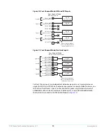
Page 34: ...ded Audio SDI n 4 BNC w Embedded Audio HD SD Video Processor 1 HD SD Video Processor 2 HD SD Video Processor 3 HD SD Video Processor 4 SDI In 5 SFP SDI In 6 SFP SDI In 7 SFP SDI In 8 SFP Four Channel Mode All incoming embedded audio is disembedded and sent to Audio Processor Signal W Signal X Signal Y Signal Z SFP Input SDI In 1 BNC SDI In 2 BNC SDI In 3 BNC SDI In 4 BNC SDI In 5 SFP w Embedded Au...

Page 35: ...annel Mode Signal W Signal X Signal Y Signal Z BNC SFP Inputs SDI In 1 BNC w Embedded Audio SDI In 2 BNC w Embedded Audio SDI In 3 BNC SDI In 4 BNC HD SD Video Processor 1 HD SD Video Processor 2 HD SD Video Processor 3 HD SD Video Processor 4 SDI In 5 SFP w Embedded Audio SDI In 6 SFP SDI In 7 SFP w Embedded Audio SDI In 8 SFP All incoming embedded audio is disembedded and sent to Audio Processor...

Page 36: ... to Audio Processor Signal Y Dual Stream Signal Z Dual Stream Four Channel Mode BNC SFP Dual Stream Input SDI In 1 BNC w Embedded Audio SDI In 2 BNC SDI In 4 BNC SDI In 3 BNC SDI In 6 SFP SDI In 7 SFP SDI In 8 SFP SDI In 5 SFP w Embedded Audio HD SD Video Processor 1 HD SD Video Processor 2 HD SD Video Processor 3 HD SD Video Processor 4 SDI A SDI B SDI A SDI B Four different signals each duplicat...

Page 37: ...r 3 HD SD Video Processor 4 SDI Out 4 BNC SDI Out 2 BNC SDI Out 5 SFP w Embedded Audio SDI Out 6 SFP SDI Out 7 SFP w Embedded Audio SDI Out 8 SFP SDI Out 1 BNC w Embedded Audio SDI Out 3 BNC w Embedded Audio Signal W Signal X Signal Y Signal Z Two different Dual Stream putputs each duplicated four times Dual Stream Output Four Channel Mode HD SD Video Processor 1 HD SD Video Processor 2 SDI Out 5 ...

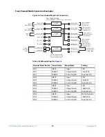
Page 38: ...1080p SDI In 6 SFP SDI In 5 SFP HD SD Video Processor 3 SDI In 8 SFP w Embedded Audio SDI In 7 SFP w Embedded Audio All incoming embedded audio is disembedded and sent to Audio Processor Signal X Output Down Convert to 270Mb SD 525i Signal Y Output Down Convert to 3G HD 1080p Signal Y 3G 2K SDI In 3 BNC w Embedded Audio SDI Out 6 SFP w Embedded Audio Four Simultaneous Frame Sync Conversions Table ...

Page 39: ...al X SDI B only Signal Y SDI B only Signal Z SDI A only Dual Stream input videos separated and routed to different connectors with each signal duplicated once All incoming embedded audio is disembedded and sent to Audio Processor SDI In 1 BNC w Embedded Audio SDI In 2 BNC SDI In 4 BNC SDI In 3 BNC SDI In 6 SFP SDI In 7 SFP SDI In 8 SFP SDI In 5 SFP w Embedded Audio SDI A SDI B SDI A SDI B Signal V...

Page 40: ...o SDI In 4 BNC w Embedded Audio SDI In 5 SFP SDI In 6 SFP SDI In 7 SFP SDI In 8 SFP Signal Z All incoming embedded audio is disembedded and sent to Audio Processor 5 8 Quad LInk Input Single Channel Mode 4K UHD Video Processor SDI In 5 SFP w Embedded Audio SDI In 6 SFP w Embedded Audio SDI In 7 SFP w Embedded Audio SDI In 8 SFP w Embedded Audio SDI In 1 BNC SDI In 2 BNC SDI In 3 BNC SDI In 4 BNC A...

Page 41: ...dded audio Figure 22 Single Channel Mode Quad Link Outputs All incoming embedded audio is disembedded and sent to Audio Processor Signal Z Dual Stream Single Channel Mode Dual Stream Input SDI In 1 BNC w Embedded Audio SDI In 2 BNC SDI In 3 BNC SDI In 4 BNC SDI In 5 SFP SDI In 6 SFP SDI In 7 SFP SDI In 8 SFP 4K UHD Video Processor SDI A SDI B Only one of the Dual Streams is routed to the Video Pro...

Page 42: ...mbedded Audio SDI Out 6 SFP w Embedded Audio SDI Out 1 BNC w Embedded Audio SDI Out 2 BNC w Embedded Audio SDI Out 3 BNC w Embedded Audio SDI Out 4 BNC w Embedded Audio SDI Out 7 SFP w Embedded Audio SDI Out 8 SFP w Embedded Audio Single Link Output Signal Z Signal Z Signal Z Signal Z Signal Z Signal Z Signal Z Signal Z Eight copies of the same signal on all outputs Dual Link Output Single Channel...

Page 43: ...B 4K UHD Video Processor SDI In 1 BNC w Embedded Audio SDI In 2 BNC w Embedded Audio SDI In 3 BNC w Embedded Audio SDI In 4 BNC w Embedded Audio SDI In 5 SFP SDI In 6 SFP SDI In 7 SFP SDI In 8 SFP SDI Out 5 SFP w Embedded Audio SDI Out 6 SFP w Embedded Audio SDI Out 1 BNC w Embedded Audio SDI Out 2 BNC w Embedded Audio SDI Out 3 BNC w Embedded Audio SDI Out 4 BNC w Embedded Audio SDI Out 7 SFP w E...

Page 44: ... Up The following workflow powers up a default FS4 and demonstrates some example alarms Setup Ensure the FS4 is completely disconnected all video audio network and power connector ports are empty Procedure 1 Connect both FS4 power cords to mains AC and allow time for the unit to boot up Observe the front panel LEDs SDI Out 7 SFP SDI Out 8 SFP SDI Out 5 SFP w Embedded Audio SDI Out 6 SFP SDI Out 4 ...

Page 45: ...report 1080i59 and an OK status for SDI 1 This indicates no alarm condition exists 5 Disconnect one of the power cords leaving the other attached The front panel PWR LED will light red for the power supply with the removed cord The PS status will report PS1 or 2 OFF 6 Reconnect the power cable The PWR LED for that power supply will light blue and the power supply status will report OK This workflo...

Page 46: ...oth Four Channel and Single Channel mode These front panel menu settings are accessed via the three System buttons VIDEO CONFIG and AUDIO The Channel Select AES menus and associated LEVEL and DELAY menu parameters for AES and MADI also affect the FS4 in both operating modes Separate MAP parameters for audio routing however are saved for each Video Processor so changing mapping in one operating mod...

Page 47: ...at parent parameter is turned on can display child menus of related parameters When the Hidden Menus parameter is set to Hide Inactive these child menus are hidden when the parent parameter is off Some menu names contain a decimal dot number and zero which indicates there are a group of related parameters Example 1 0 ProcAmp is the parent menu of the 1 1 through 1 4 child menus NOTE In this chapte...

Page 48: ... Processors 2 4 Display Description IN1 Input Source Format OUT1 Output Source Format IN2 Input Source Format OUT2 Output Source Format Selected physical video 1 input detected format Selected video output 1 format selected audio input used on output Selected physical video 2 input detected format Selected video output 2 format selected audio input used on output Display Description IN Input Sourc...

Page 49: ...ate Status Video input source alarm status Selected Genlock source alarm status System Output Frame Rate 59 29 23 98 50 25 60 30 24 Display Description SDI1 Status SDI5 Status SDI2 Status SDI6 Status SDI3 Status SDI7 Status SDI4 Status SDI8 Status Statuses for SDI inputs 1 8 Format No Input No SFP Display Description Monit Status Fmt Status Crop Status Output selected for monitoring Vid1 4 Out Out...

Page 50: ...ogin via the front panel parameter you must then go to the browser interface to perform a login each time you access the FS4 The browser presents the login screen first requiring you to log in before you can access any other browser screens The password is initially set to the default value but you can change it using the Remote browser screen The default password is password NOTE If authenticatio...

Page 51: ...e same GPI input trigger could cause different actions on each channel In Single Channel Mode each GPI input can only trigger one action on that Video Processor Caution GPI Inputs can be used to trigger Presets When you recall a Preset Configuration the recalled preset immediately replaces the system s existing configuration All previous settings are lost unless you have previously stored them in ...

Page 52: ... Vid n ARC H CP Vid n ARC PLBX Vid n ARC V CP Vid n ARC 14X9 Vid n DC Crop Vid n DC ANA Vid n DC 14X9 Vid n DC AuAFD Vid n DC LTBX Vid n UC 4X3PB Vid n UC14X9PB Vid n UCFLSCR Vid n UC LBFUL Vid n UC WDZM Vid n UC Custom Performs no action Recalls the specified PRESET configuration for the current FS4 operating mode Freezes the current video frame at its outputs Freezing stops when the GPI trigger ...

Page 53: ...or genlock either automatically or explicitly 3 1 Mon 2K Crop This parameter selects whether to crop 2K HDMI monitor output rasters to 1920 wide and has no effect on the SDI monitor output 3 2 HDMI RGB Range This parameter selects the output range for the HDMI monitor output and has no effect on the SDI monitor output Full allows a range of 0 255 and SMPTE limits the range to 16 to 235 see note fo...

Page 54: ... as shown Figure 28 Dual Stream 3G DEMUX Schematic See Figure 12 Four Channel Mode Dual Stream Inputs on page 36 and Figure 21 Single Channel Mode Dual Stream Input on page 41 for more information 4 2 SDI2 Input Protect This parameter allows you to protect Input SDI 2 from being taken by a Dual Stream selection made with SDI1 3G Detect above In the Normal setting default the SDI 2 video signal alw...

Page 55: ...routes the input signal assigned to each video processor to the output of that video processor e g Vid1 outputs are SDI1 and SDI5 All video processor input SDI signals must be locked to each other and the Genlock Source must be set to one of the SDI inputs assigned to a video processor input CONFIG Menu Group The CONFIG Menu Group includes parameters for setting up the FS4 s network system name SN...

Page 56: ...iguration used by the FS4 Consult your network administrator about how to set this value 3 2 IP Address This parameter determines the static IP address used by the FS4 for TCP IP networking Consult your network administrator about how to set this value Octet Value Entry Procedure Set the octets numbers between periods values as follows 1 Push ADJUST momentarily to enter edit mode 2 Turn SELECT to ...

Page 57: ... MM SS SS SS The value is 12 digit hexadecimal where the first half identifies the manufacturer and the second half identifies the unique serial number 4 SNMP Enable Parameters The following parameters are used to setup the FS4 SNMP Simple Network Management Protocol feature 4 0 SNMP Enable 4 1 SNMP Trap Destination 1 4 2 SNMP Trap Port 1 4 3 SNMP Trap Destination 2 4 4 SNMP Trap Port 2 Refer to C...

Page 58: ...e processor format You can suppress the Reference alarm is you wish NOTE For proper operation the Input reference signal must be stable and properly terminated using a 75 ohm terminator on either the unused loop connector or the last piece of downstream equipment to which the Ref Video is connected 8 Hidden Menus This parameter lets you choose whether to hide or show inactive menus 9 Screen Saver ...

Page 59: ...l knobs simultaneously to reboot During reboot the display shows Rebooting goes dark momentarily and then shows the percentage of progress as the system reboots Reboot should take no longer than 90 seconds AUDIO Menu Group The following descriptions explain the AUDIO Menu Group which allows you to make adjustments to the FS4 s sample rate converters Mix Down Modes and some other system wide settin...

Page 60: ... 11MADIFiberSRC Mode These parameters control the use of sample rate converters for the incoming MADI Fiber audio This setting affects all 64 MADI Fiber input channels In Auto mode normal PCM audio passes through the Sample Rate Converters and gets converted as appropriate If any of the active signal pairs are non PCM the SRC is turned off for all audio inputs Auto default On Off The system decide...

Page 61: ... using the two Mix Down Modules built into the FSI X Audio Processor The default 5 1 to 2 ch mix down equation is Left Ch Output LF 3dB CTR 3dB LR Right Ch Output RF 3dB CTR 3dB RR The default 7 1 to 2 ch mix down equation is Left Ch Output LF 3dB CTR 3dB LS 3dB LR Right Ch Output RF 3dB CTR 3dB RS 3dB RR These default settings can be adjusted using the front panel menus or web interface NOTE The ...

Page 62: ...n Output Lft Rt Level The level of the Left and Right mixer output signal can be adjusted plus or minus 18 dB in half dB increments using these menu controls Default is 0 dB unity 3 0 Mix Down 2 Mode 4Ch only Same as Mix Down 1 Mode menu and related sub menus except for the Mix Down 2 mixer SDI 1 default SDI 2 8 Selects the indicated source The channel assignments are as follows All unused channel...

Page 63: ...els to default settings Resets the Mix Down 2 mixer levels to default settings Off default No Global output configuration is imposed When Off all other AUDIO OUTPUT menus are enabled and displayed SDI1 SDI2 8 4Ch only AES EBU MADI BNC MADI Fiber The selected source channels are routed to all the FS4 audio output channels Sig Gen 1KHz Sig Gen 400Hz Mute The selected tone or mute is routed to every ...

Page 64: ...tings are lost unless you have previously stored them in another preset configuration or an exported file Caution In Four Channel Mode each Preset saves all the settings for all four channels Storing and recalling a Preset will affect all the settings for all four channels in that mode Care must be taken to establish a policy for the use of FS4 Presets especially if the FS4 is operated in Four Cha...

Page 65: ...enu Group IMPORTANT In Four Channel Mode the settings in this menu group apply only to the selected Video Processor VID1 VID 4 1 Input These parameters perform input video source selection for the Video Processor Source Memory Changing the Video Input selection automatically selects new values for Proc Amp parameters and Color Corrector RGB parameters Each video source remembers its own Proc Amp a...

Page 66: ...utput frames being dirty having fields from different original frames Another commonly used film cadence is 2 3 3 2 which has only one dirty frame but results in motion that is slightly less smooth Many other more exotic film cadences exist but they are rarely used Film cadence removal reverses pulldown Reverse Telecine and can turn interlaced video originally sourced from film with pulldown back ...

Page 67: ...MPTE 352 Payload ID data and respond accordingly If there is no SMPTE 352 information the system will assume that 23 98 24 fps sources are PsF and 25 29 97 30 fps sources are interlaced Progressive When Progressive is selected the system will assume that all sources are PsF even if there is SMPTE 352 data to the contrary Interlaced When Interlaced is selected the system will assume that all source...

Page 68: ...ways inserts a Full Frame AFD code 8 which indicates that the image is full frame with an aspect ratio that is 16 9 Pillarbox Always inserts a 4 3 center AFD code 9 which indicates that the image has a 4 3 aspect ratio as a horizontally center pillarbox image within the 16 9 frame Letterbox Always inserts a 16 9 with complete 16 9 image protected AFD code 10 which indicates that the image is full ...

Page 69: ...video This is traditionally called HD DTV or 708 captioning The data formatting and encoding for 708 captions is very different from the data contained in 608 SD captioning reflecting the added features and capabilities available with the CEA 708 standard When the Caption Translator is on the FS4 Upconverter automatically translates incoming line 21 captions to CEA 708 format and inserts the VANC ...

Page 70: ...ion data on the SD input If no line 21 caption is present the FS4 passes the video unaltered If line 21 data is detected the FS4 copies the data blanks line 21 and reinserts translated captioning on the transformed output if parameter 18 Caption Xlator is On If the Caption Translator is Off the output will not contain captioning This is the setting to use if your SD input video sometimes contains ...

Page 71: ... parameters adjusts the Gain Black Level and Gamma for color Green same as Color Red described above 2 7 2 9 Color Blue This set of parameters adjusts the Gain Black Level and Gamma for color Red Blue same as Color Red described above 3 0 Video Legalizer These parameters allow adjustment of signal levels to meet legal broadcast requirements When set to Off the Video Legalizer is not enabled and th...

Page 72: ...utput Format Selection Constraint Available frame rates depend on System menu 1 Output Frame Rate on page 53 parameter setting Output Timing Memory Changing the Output Format selection automatically selects new values for H V timing parameters see 1 Output Frame Rate on page 53 Each Output Format mode remembers its own H and V timing settings Output Format Mapping The Output Format selection is re...

Page 73: ...ngle connector Sets the output transport to 1 5Gb Dual Link two connectors ST 372 Sets the output transport to 3Gb Level B DL single connector When Level B is selected a sub menu becomes available to choose the Video Processor s VID1 Vid1 default Vid1 Vid 2 Selects only the Vid 1 Processor signal for output Select both the Vid1 and Vid2 Processor signals for output Dual Stream VID2 Vid2 default Vi...

Page 74: ...RC performed on an incoming selected SD source input This parameter has an effect only when the input and output are both SD 525i or 625i NOTE Any Custom Size Pos values only available in Four Channel Mode will be applied on top of this settings QuadLnk Lvl A default QuadLnk Lvl B Sngl Lnk LvlA Dual Link Sngl Lnk LvlB Sets the output transport to Quad Link Level A four connectors Sets the output t...

Page 75: ... picture scaling is such that the visual effect closely resembles an SD to HD upconvert NOTE Any Custom Size Pos values only available in Four Channel Mode will be applied on top of this settings H Crop Pillarbox V Crop 14 9 Off no conversion Letterbox 4 3 4 3 Converts To These displays on 4 3 4x3 Pillar default 14x9 Pillar Full Screen LB to Full Wide Zoom Results in 4x3 image at center screen wit...

Page 76: ...ownconvert Mode is set to Auto AFD Full Screen 4 3 Pillar LB to Full 14 9 Pillar Wide Zoom 1 6 9 4 3 4 3 Upconverts To These displays on 16 9 Crop default Anamorphic 14 9 Auto AFD Letterbox Image is cropped to fit new screen size HD image is converted to full screen SD with a 16x9 aspect ratio anamorphic Image is reduced slightly with aspect ratio preserved Black is added top and bottom and the le...

Page 77: ...ing of parameter 1 1 AFD Out on page 68 SCALE Menu Group IMPORTANT In Four Channel Mode the settings in this menu group apply only to the selected Video Processor VID1 VID 4 Custom Conversion Settings The custom settings determine the image size and shape for Upconvert mode if you choose the Custom selection for those modes Custom settings are stored separately for each Conversion Mode Values for ...

Page 78: ...This parameter changes the bottom picture crop position Off default On Sets this parameter and related custom size pos parameters to off Enables this parameter and related custom size position parameters 100 default 10 to 200 Maintains 100 picture size for the selected format Enables changing the picture size 0 000 default 0 500 to 0 500 Maintains the normal 100 aspect ratio for the selected forma...

Page 79: ... parameters The Region of Interest menu is not displayed when Active Format Description AFD is in control of the Conversion Mode Custom Size and Position settings work interactively with ROI but Custom Crop settings are disabled Custom Size Pos is also temporarily disabled while in the ROI Setup mode 2 1 ROI Left This parameter sets the left boundary of the ROI 2 2 ROI Right This parameter sets th...

Page 80: ...tte Hue This parameter determines the Matte Hue of the background fill NOTE On the front panel as you turn the Matte Hue ADJUST knob the values wrap from 359 back to 0 degrees TIMING Menu Group IMPORTANT In Four Channel Mode the settings in this menu group apply only to the selected Video Processor VID1 VID 4 These parameters adjust Video Processor horizontal and vertical output timing in referenc...

Page 81: ... various video frame rates Variable Adjustment range increments from 0 to the width of the line in pixels The maximum varies depending on the format chosen Default 0 Variable Adjustment range increments from half a frame up to a half a frame down in single line increments The maximum varies depending on the format already chosen Default 0 Table 10 Output Timing Ranges Output Frame Rate Horizontal ...

Page 82: ... 1 Test Pattern Gen This parameter turns selects whether test pattern is output by that Video Processor NOTE Normal output can be a version of its currently selected input a Sidebar or Letterbox display Black or a Freeze of last good video depending on the current configuration 2Kx1080p23 98 2Kx1080p24 0 2749 562 562 2Kx1080p25 0 2639 562 562 2Kx1080p29 97 2Kx1080p30 0 2199 562 562 2Kx1080p50 0 26...

Page 83: ...audio EMBED selects SDI embedded audio for control The FS4 supports 16 embedded audio channels for each video channel AES selects both AES and MADI audio for control each with their own set of parameter menus The FS4 supports up to 16 AES channels eight pairs and up to 64 MADI audio channels When the EMBED or AES button is selected the three Audio buttons on the right are used to select a category...

Page 84: ...DI1 audio input channels The default Unity setting applies normal non inverted phase to all the input channels When Adjust mode is selected After selecting an individual channel adjustment menu the ADJUST knob toggles the Phase value shown between Normal and Invert When Invert is selected the phase of the audio input on that channel will be inverted Switching from Unity to Adjust will apply the in...

Page 85: ... Delay Menus When EMBED is selected the following SDI Embedded Audio menus are available 1 0 SDI1 Delay This parameter selects the Audio Delay Mode for the eight SDI1 audio input channel pairs Delay operates on channel pairs only Delay cannot be adjusted on any single channel Channel pairs are grouped as Channel 1 and 2 Channel 3 and 4 Channel 15 and 16 The default Global setting applies the curre...

Page 86: ...Sixty four MADI Fiber Level and related submenus are available NOTE For level adjustment information see 1 0 SDI1 Delay on page 85 MAP Menu Group IMPORTANT The settings in this menu group apply to the currently selected audio category EMBED or AES MADI These settings are NOT shared with both Four Channel and Single Channel modes The MAP menus provide FS4 audio routing controls Any audio input can ...

Page 87: ... 1 1 16 SDI1 Output Channel When Map is selected each listed source can be mapped to each output channel of the currently selected output menu 2 0 4 0 SDI2 4 Audio Out See 1 0 Vid 1 Audio Out on page 87 SDI1 8 AES EBU MADI BNC MADI Fiber The selected source channels are routed to the corresponding output channels Mix Down 1 L R The stereo output of the Mix Down 1 Module is routed to the output cha...

Page 88: ... browser s address field By default the FS4 is set to automatically connect to your network s DHCP server to get an IP address and other network configuration data You will find the IP address in the STATUS Menu Group as follows 1 Press the STATUS button on the FS4 front panel 2 Turn the SELECT knob until you reach status display with the FS4 name at the top 3 Enter the IP address shown in the IP ...

Page 89: ...such as Cion and other FS models If you right click any system in the list and select Identify the ID LEDs on the unit will blink to identify it Click on Identify again to stop the blinking Another way to identify systems is to notice which system s EXT front panel LED flashes when you change any setting from a remote control device such as the web browser Figure 34 FS4 Web Interface Main Status S...

Page 90: ... alternative value The FS4 will immediately operate with the new setting Slider Operation Some screens contain slider controls for setting values To set a value you can click on a slider to select it and then use the mouse to drag the slider to the position you desire For fine tuning while the slider is selected highlighted by a blue border use the keyboard left and right arrow keys to change the ...

Page 91: ...tem ID LEDs Click the gear shaped icon in the Network pane or select Network from the Menu list on the left side of the screen to open the Network Configuration screen listing FS4 network settings The Network Configuration screen allows you to view and change your FS4 s network settings and then click Apply to activate them See Networking on page 29 for detailed setup instructions for connecting t...

Page 92: ...atic Addr Select automatic IP address assignment from the LAN DHCP server If the FS4 cannot find a DHCP server it fails over to the static IP address Assign a static IP address manually The factory default static IP address 192 168 0 2 Variable If IP Address Type is set to DHCP the IP address is set automatically by the network DHCP server and cannot be entered here If IP Address Type is set to St...

Page 93: ... the Alarms panel To close the window press the ESC key or click the X in the upper right corner The Alarm Configuration display provides control over these alarm settings Power Supply Alarm see 5 1 5 2 Power Supply 1 2 Alarm on page 58 Video Format Alarm see 6 Vid Format Alarm on page 58 Reference Alarm see 7 Reference Alarm on page 58 Alarm Configuration popup display FS4 Alarms display button g...

Page 94: ...www aja com 94 FS4 Frame Synchronizer Converter v1 1 Status Screen Figure 35 Status Screen Top Four Channel Mode Figure 36 Status Screen Bottom Four Channel Mode ...

Page 95: ...lor Corrector RGB is On or Off Shows whether Custom conversion AFD and ROI are On or Off Shows the current background signal Black or Matte Genlock Genlock Source Shows the source of the genlock reference and its format Video Input Status SDI 1 8 Shows the status of each Video input BNCs and SFPs Audio Output Global Audio Output Right clicking on the Global Audio Out parameter value lets you selec...

Page 96: ...er sets the name of the FS4 system To change the System Name click on and drag the cursor across the displayed name and type in a new name Hit enter when finished or click outside the name control to cancel The System Name is the same for both the Four Channel and Single Channel modes of operation FS4 Mode Selects whether the FS4 will operate in Four Channel or Single Channel mode A confirm dialog...

Page 97: ...twork will be listed under Other Devices below Computers and Media Devices If your system does not have network discovery enabled you may need to enable it following the Windows help instructions to make network devices visible in the Windows Network window UPnP Proxy UPnP Proxy enables the FS4 to serve as a proxy for other AJA devices allowing them to be discovered on a Windows network through th...

Page 98: ...nt panel display menus The only difference is parameters are set using webpage controls drop down menus slider adjustments instead of control knobs Complete descriptions of these parameters are accessible using the following cross references 1 Output Frame Rate on page 53 2 Genlock Source on page 53 3 1 Mon 2K Crop on page 53 3 2 HDMI RGB Range on page 53 3 3 Monitor Map on page 54 4 1 SDI1 3G Det...

Page 99: ...play menus The only difference is parameters are set using webpage controls drop down menus slider adjustments instead of control knobs Complete descriptions of these parameters are accessible using the following cross references 1 MADI Output Mode on page 59 2 1 2 8 SDI 1 8 SRC Mode on page 60 2 9 AES SRC Mode on page 60 2 10 MADI BNC SRC Mode on page 60 2 11 MADI Fiber SRC Mode on page 60 3 0 Mi...

Page 100: ...r failed saves recalls exports and imports Presets Screen Controls Factory Preset Factory Preset recalls all editable video and audio parameters to their factory default settings Individual presets user preferences and Network settings such as the IP Address are not affected Recall Factory Preset changes the settings for both Single Channel and Four Channel FS4 operating modes to their factory def...

Page 101: ...import a preset file on your computer into the preset register associated with the selected button A dialog box warns you that the operation will overwrite the current preset contents with the file contents You can only import presets from a FS4 Export Presets 1 40 All Export All lets you save the contents of all presets to a file on your computer The file gets exported to the default download loc...

Page 102: ...panel interact with the browser parameters available on an attached computer and vice versa For example once the Remote Control parameter is set to Local Only from either the browser or front panel all future settings will only be able to be changed from the front panel The opposite is true if set to Remote Only However the Remote Control parameter is always available from the front panel regardle...

Page 103: ...cal software copy Follow the prompts to load the new firmware into the FS4 See Software Update Installation on page 32 for more information Video Channel Screens The Video Channel screens control the FS4 s video signal processing of that channel either four or one depending on mode In Four Channel Mode four menu groups are selected on the left In Single Channel Mode only one menu group is availabl...

Page 104: ...s screen are accessible using the following cross references 1 Input on page 65 2 Loss of Input on page 66 3 Reverse Telecine on page 66 4 Input Scan Format on page 67 Format Screen Complete descriptions of the parameters on this screen are accessible using the following cross references 1 Output Format on page 72 ...

Page 105: ...I1 4 on page 73 3 0 Link Config SDI5 8 on page 74 4 Output Image Mapping on page 74 6 Upconvert Mode on page 75 7 Downconvert Mode on page 76 Timing Screen Complete descriptions of the parameters on this screen are accessible using the following cross references 1 Output Timing H on page 81 2 Output Timing V on page 81 3 Frame Delay on page 82 ...

Page 106: ...ptions of the parameters on this screen are accessible using the following cross references Custom Conversion Settings on page 77 Region of Interest ROI on page 79 Keyer Screen Complete descriptions of the parameters on this screen are accessible using the following cross references 1 Background Fill on page 80 2 Sidebar Edge on page 80 ...

Page 107: ... 1 Matte Luma on page 80 11 2 Matte Chroma on page 80 11 3 Matte Hue on page 80 Test Gen Screen Complete descriptions of the parameters on this screen are accessible using the following cross references 1 Test Pattern Gen on page 82 2 Test Pattern on page 83 ...

Page 108: ... accessible using the following cross references 1 0 Proc Amp Enable YUV on page 70 2 0 Color Corrector RGB on page 71 3 0 Video Legalizer on page 71 ANC Screen Complete descriptions of the parameters on this screen are accessible using the following cross references 1 1 AFD Out on page 68 1 2 AFD VANC Output Lines on page 68 ...

Page 109: ...tions of the parameters on this screen are accessible using the following cross references 1 Freeze Output on page 83 Embedded Audio Channel Screens The Embedded Audio Channel browser screens display Level Delay and Mapping controls for the Embedded audio channels When the SDI output signal has multiple links the audio is always embedded on the first link of the SDI output channel ...

Page 110: ... descriptions of the parameters on this screen are accessible using the following cross references EMBED Level Menus on page 84 Embed Delay Screen Complete descriptions of the parameters on this screen are accessible using the following cross references EMBED Delay Menus on page 85 ...

Page 111: ...4 0 SDI2 4 Audio Out on page 87 AES and MADI Audio Channel Screens The AES Audio Channel browser screens display Level Delay and Mapping controls for the AES MADI BNC and MADI Fiber audio channels AES MADI Level Screen The parameters on this screen are similar to those for the Embedded Audio Channel screens except they apply to either AES or MADI audio inputs For more information see EMBED Level M...

Page 112: ...ns except they apply to either AES or MADI audio inputs For more information see EMBED Delay Menus on page 85 AES MADI Map Screen The parameters on this screen are similar to those for the Embedded Audio Channel screens except they apply to either AES or MADI audio inputs For more information see 1 0 Vid 1 Audio Out on page 87 2 0 4 0 SDI2 4 Audio Out on page 87 ...

Page 113: ...ctivating SNMP trap destinations must also be defined with fixed IP addresses When SNMP is enabled one or more of these alarms may be sent by the FS4 to the client network management system NMS as a trap message FS4 power supply 1 Alarm FS4 power supply 2 Alarm No Reference Alarm Incompatible Reference Alarm Format incompatibility Video Proc Alarm Format incompatibility Video Proc 1 Alarm Format i...

Page 114: ... parameters are described later in this chapter Front Panel Octet Value Entry Procedure Set the octets numbers between periods values as follows 1 Push ADJUST momentarily to enter edit mode 2 Turn SELECT to select the octet you want to edit indicated by blinking 3 Turn ADJUST to enter the new value If you need to revert to the previous setting undo changes push SELECT 4 Push ADJUST momentarily to ...

Page 115: ...mber and exit the parameter the port changes immediately to the new value 4 3 SNMP Trap Destination 2 This parameter determines the secondary SNMP Trap Destination IP address where trap messages issued by the FS4 will be sent if desired This parameter is similar to 4 1 SNMP Trap Destination 1 above The default is 192 168 0 3 4 4 SNMP Trap Port 2 This parameter determines the SNMP Trap Port used fo...

Page 116: ...4 fields YCbCr 4 2 2 10 bit Video Input Digital 4 x 3G SDI inputs 4 x BNC 4 x 3G SDI inputs 4 x Fiber or BNC optional SFP modules SFP fiber modules 3G SDI dual LC single LC or single SC SMPTE 297 SFP fiber module 12G 6G SDI dual LC SMPTE 297 SFP coax module 12G 6G SDI dual HD BNC 12G 6G 3G HD SD SMPTE 259 292 424 2081 2082 Single Link 12G 6G SDI with optional SFP module Quad Link 3G SDI Level A or...

Page 117: ... 4K UltraHD output pixel mapping Monitor Output Digital 1 x BNC 1 x 3G SDI output 3G SDI HD SD SMPTE 259 292 424 10 bits 1 x HDMI 1 x HD output 2K HD SD HDMI v1 4a Monitored Video Processor output video and audio is simultaneously output on both connectors 4K UltraHD down converted to 2K HD Crop control on HDMI output Video Processing Motion adaptive deinterlacer Proc amp controls Color corrector ...

Page 118: ... a 16 9 screen this setting will introduce a small aspect ratio change Down Conversion Hardware 10 bit Anamorphic fullscreen Letterbox image is reduced with black top and bottom added to image area with the aspect ratio preserved Crop image is cropped to fit video output format Aspect Ratio Conversion for SD to SD Letterbox Transforms SD anamorphic material to a letterboxed image H Crop Produces a...

Page 119: ... ST Fiber 128 Channels 24 bit AES 10 Audio Processing 277 x 208 mono audio matrix route 1 to 1 1 to many Inputs 128 embedded 16 AES 128 MADI 2 stereo mixdowns 3 tone generator Outputs Four Ch Mode 16 AES 128 MADI 64 embedded Outputs Single Ch Mode 16 AES 128 MADI 16 embedded Input adjustment controls for each channel Gain 18 to 18 dB in 0 5 dB steps Phase invert Input adjustment controls for each ...

Page 120: ...edded web server for remote control Front Panel Display Keypad with status LEDs Two rotary push knobs Comprehensive alarm indicators Presets Each mode supports 40 Presets GPI 1 x 25 pin D Connector Four optically isolated GPI inputs Four optically isolated GPO outputs Size w x d x h 17 5 x 16 x 1 75 1RU 444 5mm x 406 5mm x 44 45mm Weight 7 9 lb 3 6 kg Power 100 240 VAC 50 60 Hz Dual redundant powe...

Page 121: ...Converter v1 1 Environment Operating Temperature 0 to 40 degrees C 32 to 104 degrees F Storage Temperature 40 to 60 degrees C 40 to 140 degrees F Operating Relative Humidity 10 to 90 noncondensing Operating Altitude 3 000 meters 10 000 feet ...

Page 122: ...und may only be used as references when isolation is not required All four GPI inputs are internally pulled high through a 10K ohm resistor to an isolated 5V supply so that a relay contact closure or any device sinking at least 0 4 mA to ground will register a logic low All four GPI outputs are 5V TTL compatible sourcing up to 6mA and sinking up to 4mA each The following illustration shows typical...

Page 123: ... channel handles a pair of digital audio signals 16 total per connector The top connector is for digital audio input channels 1 16 and the bottom connector is for digital audio output channels 1 16 1 14 20 24 25 13 7 GPI Out 4 xmit xmit Optical Relay SSR To Tally Lamp etc GPI GND 4 GPI GND 1 GPI In 1 V G G G 15 16 13 14 G 5 6 G 1 2 G 9 10 11 12 G 7 8 G 3 4 AES Channels G Ground To MUX into unbalan...

Page 124: ...on between the equipment and receiver Connect the equipment into an outlet on a circuit different from that to which the receiver is connected Consult the dealer or an experienced radio TV technician for help FCC Caution This device complies with Part 15 of the FCC Rules Operation is subject to the following two conditions 1 This device may not cause harmful interference and 2 this device must acc...

Page 125: ...s issued for specific countries available on request Emissions EN 55032 2012 CISPR 22 2008 EN 55022 2010 EN 61000 3 2 2006 A1 2009 A2 2009 EN 61000 3 3 2008 Immunity EN 55103 2 2009 EN 61000 4 2 2009 EN 61000 4 3 2006 A1 2008 A2 2010 EN 61000 4 4 2004 A1 2010 EN 61000 4 5 2006 EN 61000 4 6 2009 EN 61000 4 11 2004 Environments E2 E3 and E4 The product is also licensed for additional country specifi...

Page 126: ... interference may occur in which case the user may be required to take corrective actions This symbol on the product or its packaging indicates that this product must not be disposed of with your other household waste Instead it is your responsibility to dispose of your waste equipment by handing it over to a designated collection point for the recycling of waste electrical and electronic equipmen...

Page 127: ...ind Advertencia Lea y siga todas las instrucciones y advertencias marcadas en el producto o incluidas en la documentación Aviso Leia e siga todos os avisos e instruções assinalados no produto ou incluídos na documentação Avviso Leggere e seguire tutti gli avvisi e le istruzioni presenti sul prodotto o inclusi nella documentazione Warning Do not use this device near water and clean only with a dry ...

Page 128: ...ny heat sources such as radiators heat registers stoves or other apparatus including amplifiers that produce heat Avertissement N installez pas l appareil près d une source de chaleur telle que des radiateurs des bouches d air de chauffage des fourneaux ou d autres appareils amplificateurs compris qui produisent de la chaleur Warnung Nicht in der Nähe von Wärmequellen wie Heizkörpern Heizregistern...

Page 129: ... dentro del dispositivo el dispositivo ha sido expuesto a la lluvia o humedad o no funciona de modo normal o se ha caído Aviso Remeta todos os serviços de manutenção para o pessoal de assistência qualificado A prestação de serviços de manutenção é exigida quando o dispositivo foi danificado mediante qualquer forma como um cabo de alimentação ou ficha que se encontra danificado a quando foi derrama...

Page 130: ...ar danos devido a choques elétricos Avviso Alta tensione Questa situazione o condizione può causare lesioni a causa di scosse elettriche Warning Only use attachments and accessories specified and or sold by the manufacturer Avertissement Utilisez seulement les attaches et accessoires spécifiés et ou vendus par le fabricant Warnung Verwenden Sie nur Zusatzgeräte und Zubehör angegeben und oder verka...

Page 131: ... der zur Verfügung gestellte Stecker nicht in Ihren Anschluss passt konsultieren Sie einen Elektriker um den veralteten Anschluss zu ersetzen Advertencia No eche por tierra la finalidad del tipo de enchufe polarizado con conexión a tierra Un enchufe polarizado tiene dos espigas una más ancha que la otra Un enchufe con conexión a tierra tiene dos espigas iguales y una tercera espiga que sirve para ...

Page 132: ...l Warnung Vermeiden Sie dass auf das Netzkabel getreten oder das Kabel geknickt wird insbesondere an den Steckern den Steckdosen und am Kabelausgang am Gerät Advertencia Proteja el cable de energía para que no se le pise ni apriete en especial cerca del enchufe los receptáculos de conveniencia y el punto del que salen del equipo Aviso Proteja o cabo de alimentação de ser pisado ou de ser comprimid...

Page 133: ...huma peça que permita manutenção pelo usuário Abrir o chassi anula a garantia a menos que a abertura seja realizada por uma central de serviços da AJA ou por um local autorizado Avvertenza Non aprire lo chassis All interno non ci sono parti riparabili dall utente L apertura dello chassis invaliderà la garanzia se non viene effettuata da un centro ufficiale o autorizzato AJA Warning To meet safety ...

Page 134: ...en Glasfaserkabelanschluss am FS1 X FS2 FS3 oder FS4 schauen diese Modelle sind Lasergeräte der Klasse 1 Advertencia Los cables de fibra óptica activos emiten radiación invisible al ojo humano No mire directamente hacia el extremo de un cable de fibra óptica activo o hacia el conector de fibra óptica del FS1 X FS2 FS3 o FS4 estos modelos están clasificados como Productos Láser Clase 1 Advertência ...

Page 135: ...es insurance duties taxes and any other charges for products returned to any other locations This warranty shall not apply to any defect failure or damage caused by improper use or improper or inadequate maintenance and care AJA Video shall not be obligated to furnish service under this warranty a to repair damage resulting from attempts by personnel other than AJA Video representatives to install...

Page 136: ...ormat 58 Video Incompatibility 24 Alarms Configuration Browser Screen 93 Alphanumeric Display 19 ANC Browser Screen 108 ANC Button 22 ANC Menu Group 68 Audio Connections pinout 123 Global Output Menu 63 Reset Mapped Output Menu 63 System Audio Button 21 Audio and Video Routing Using Presets 65 Audio Features 12 Audio Menu Group Buttons 23 DELAY 23 LEVEL 23 MAP 23 Audio Processor Technical Descript...

Page 137: ...tions 25 Control Browser 13 31 88 Front Panel 12 Overview 12 SNMP 13 Control Buttons Knobs and Display 18 Conversion Procedure 16 Single Channel Mode Example 43 Conversion Example Four Channel Mode Example 38 Cooling Requirements 29 Custom Custom Aspect Menu 78 Custom Bottom Crop Menu 78 Custom H Position Menu 78 Custom Left Crop Menu 78 Custom Right Crop Menu 78 Custom Size Menu 78 Custom Size Po...

Page 138: ...Freeze Output Menu 83 Front Panel Control 12 Coarse Adjust 19 Operational Summary 19 Front Panel Description 18 FS4 Mode Menu 56 96 FS4 Modes 46 Presets 47 System Parameters 46 Video Parameters 46 G Gateway Address Default 29 Genlock Genlock Source Menu 53 Genlock Source Overview 16 Global Output Menu 63 GPI In Out Connectors 25 GPI Inputs and Outputs 13 GPIs GPI 1 4 OUT Menu 53 GPI Connections 44...

Page 139: ... MAP Menu Group 86 Matte chroma Menu 80 Matte Hue Menu 80 Matte Luma Menu 80 Menu Groups ANC 68 COLOR 70 Config 21 55 DELAY 85 FORMAT 72 FREEZE 83 Input 65 KEYER 79 LEVEL 83 MAP 86 Preset 21 64 Remote 21 50 SCALE 77 Status 21 47 System Audio 21 TIMING 80 TSTGEN 82 Video 21 Menu Page Types 47 Menus AES Delay 86 AES Input Status 49 AES SRC Mode 60 AES MADI 85 AFD Out 68 AFD VANC Output Lines 68 69 B...

Page 140: ...annel 87 SDI1 Channel Pair Delay 86 SDI1 Delay 85 SDI1 Delay Global 86 SDI1 Level 84 SDI1 Phase 84 SDI1 3G Detect 54 55 SDI2 Input Protect 54 Serial Number 59 Sidebar Edge 80 SNMP Enable 115 SNMP Trap Destination 1 115 SNMP Trap Destination 2 115 SNMP Trap Port 1 115 SNMP Trap Port 2 115 Software Version 59 Subnet Mask 57 System Name 55 96 System Status 47 Test Pattern 83 Test Pattern Gen 82 Uplin...

Page 141: ...tion Front 18 Rear Description 25 Parameter Menus 46 Ping Mac 31 Ping PC 31 Ping Test Network 31 Pinouts Audio 123 Digital Audio 123 GPI 122 Power Connection 27 Power Supply Alarm Menu 58 PWR 1 2 LEDs 23 Requirements and Warnings 29 Power Connectors 25 Power Up First Time 44 Preset Button 21 Preset Menu Group 21 64 Presets FS4 Modes 47 Interactions with GPIs 52 Presets 1 40 Menu 64 Routing Audio w...

Page 142: ...el Mode 11 Conversion Example 43 Input Example 40 Output Example 41 Technical Description 14 Slider Operation Browser Screens 90 SNMP 113 MIB 113 SNMP Alarm Traps 113 SNMP Enable Menu 115 SNMP Interface 13 SNMP Trap Dest 1 Dest 2 113 SNMP Trap Destination 1 Menu 115 SNMP Trap Destination 2 Menu 115 SNMP Trap Port 1 Menu 115 SNMP Trap Port 2 Menu 115 Software Download 32 Software Update Procedure 3...

Page 143: ... 1 Audio Out Menu 87 VID1 4 Button 22 Video System Menu Group 21 Video Format Alarm Menu 58 Video Incompatibility Alarms 24 Video Legalizer Menu 71 Video Channel Browser Screens 103 Video Conversion Procedure 16 Video Features 11 Video Menu Group Buttons 22 ANC 22 COLOR 22 FORMAT 22 FREEZE 23 INPUT 22 KEYER 22 SCALE 22 TIMING 22 TSTGEN 23 Video Parameters FS4 Modes 46 Video Processor Technical Des...

Reviews: