U-TAP Series USB 3 3G-SDI or HDMI Capture Device v1.5.2 6
www.aja.com
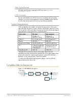
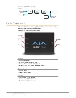
Figure 2. U-TAP SDI Block Diagram
SDI
RCVR
SDI Loop Out
SDI In with
Embedded
Audio
U-TAP-SDI
Configuration
(PC or Mac)
USB type B Port
Video Out with
2 Ch Audio
Control
Video and
Audio
Processing
USB
Interface
Cable Connections
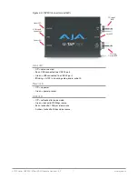
U-TAP connections are made directly to the unit’s connectors located on each
side. LEDs also report various statuses by color.
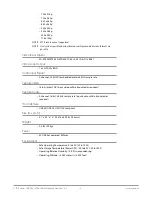
Figure 3. U-TAP HDMI Connectors and LEDs
Lock LED
Status LED
USB type B
Connector
Power LED
HDMI Input
Status LED
• Off = not connected
• Red = USB connected to a USB 2.0 port
• Green = USB connected to a USB 3.0 port
• Blinking = U-TAP is streaming video, audio, or both
Power LED
• Off = no power
• Green = power present
LOCK LED
• Off = not locked to source video
• Green = locked to SD video source
• Red = locked to HD video source


