background image

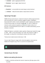
OUT terminals:

Operating Principle

WallSwitch input terminals are connected to the grid, and the output terminals
are connected to the socket or electrical appliance/system. WallSwitch
closes/opens the electric circuit, controlling the power supply by the command
of the security system user through the 

The state of WallSwitch

contacts can be switched manually: by holding the function button for 2
seconds. To make WallSwitch react to alarm or schedule automatically, you can
con gure a scenario.

WallSwitch features a protection system against voltage surge beyond the range
of 184V – 253V or overcurrent above 13А. In this case, the power supply is
interrupted, resuming after normalizing the voltage and current values.

The maximum resistive load on the relay is 3 kW.

You can check the power usage by the electrical appliance connected via
WallSwitch through the app. There is a power consumption meter.

At low loads (up to 25 W), current and power consumption indications may be displayed
incorrectly due to hardware limitations.

Connecting to the hub

Before connecting the device:

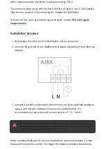
L terminal — power supply phase terminal.

N terminal — power supply neutral terminal.

N terminal — connected device neutral output contact terminal.

L terminal — connected device phase output contact terminal.

Ajax app

1. Switch on the hub and check its Internet connection (the logo glows white

or green).

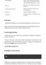
Summary of Contents for WallSwitch

Page 1: ...ed electrician should install WallSwitch WallSwitch operates only within the Ajax security system integration into third party security systems is not provided communicating with a via the protected p...

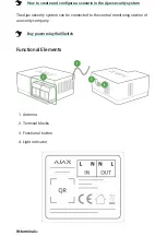
Page 2: ...the central monitoring station of a security company Functional Elements IN terminals How to create and con gure a scenario in the Ajax security system Buy power relay WallSwitch 1 Antenna 2 Terminal...

Page 3: ...253V or overcurrent above 13 In this case the power supply is interrupted resuming after normalizing the voltage and current values The maximum resistive load on the relay is 3 kW You can check the po...

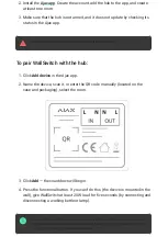
Page 4: ...account add the hub to the app and create at least one room Ajax app 3 Make sure that the hub is not armed and it does not update by checking its status in the Ajax app 1 Click Add device in the Ajax...

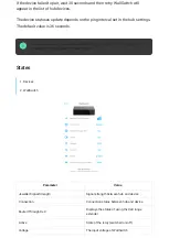
Page 5: ...witching on for the rst time WallSwitch contacts are open When deleting WallSwitch from the system contacts open States Parameter Value Jeweller Signal Strength Signal strength between hub and device...

Page 6: ...s the power supply Firmware Device rmware version Device ID Device identi er Settings Setting Value First eld Device name can be edited Room Selecting the virtual room to which the device is assigned...

Page 7: ...ght indicator blinks periodically When the functional button is pressed the light indicator lights up Functionality testing The Ajax security system allows conducting tests for checking the functional...

Page 8: ...rrect connection may cause the device to malfunction and or damage the property When installing WallSwitch in the box lead out the antenna and place it under the plastic frame of the socket The bigger...

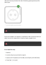
Page 9: ...the installation and operation of WallSwitch follow the general electrical safety rules and the requirements of electrical safety regulatory acts It is strictly forbidden to disassemble the device Do...

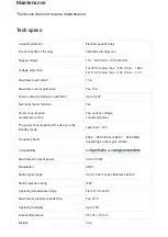
Page 10: ...Electricity meter function Yes Power consumption parameters control Yes current voltage consumed power The power consumption of the device in the standby mode Less than 1 W h Frequency band 868 0 868...

Page 11: ...for 2 years after the purchase If the device does not work correctly you should rst contact the support service in half of the cases technical issues can be solved remotely Technical support 1 WallSw...

Page 12: ...Need help In this section you ll nd detailed manuals and educational videos about all features of Ajax And in case you need help of a technical specialist we re available 24 7 Send request...

Reviews: