background image

115 

Rev 2.1 

Extended Warranty:

 An extended 7-year heat exchanger warranty to the customer follows the same conditions 

as stated above and will be as follows: 
 

Year Discount 

1-5 100% 

6 50% 

7 25% 


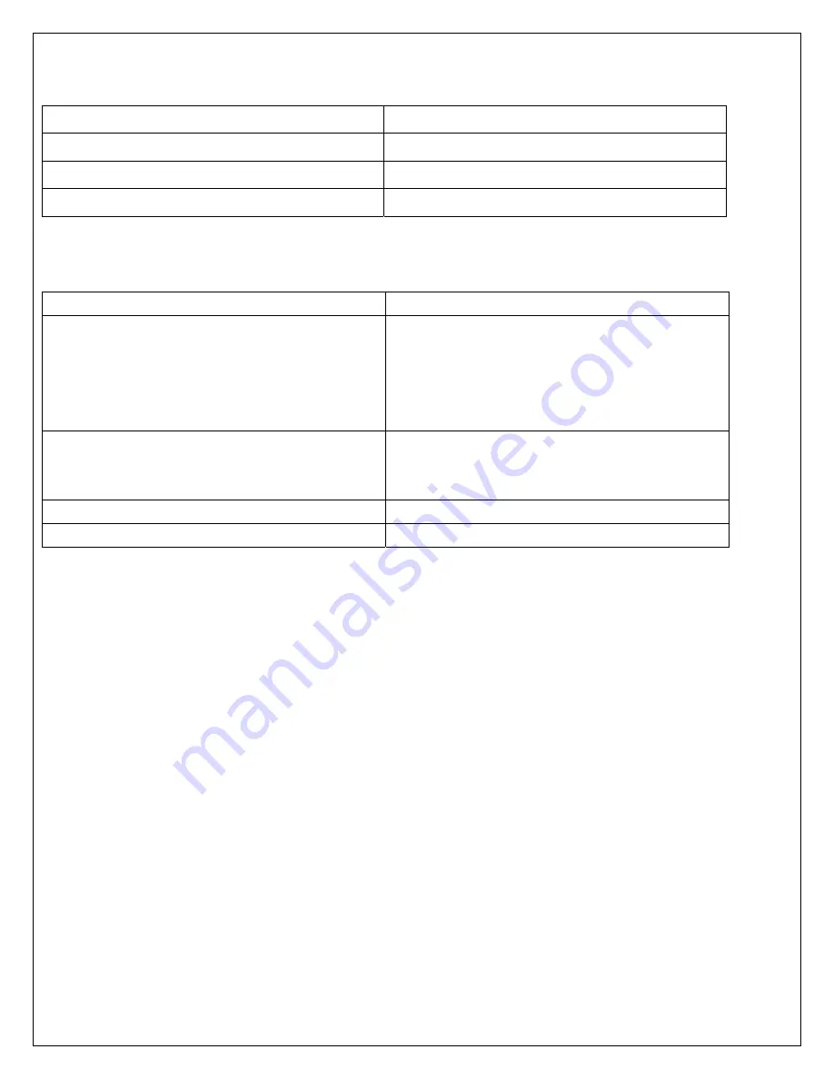
Summary of Atlas Acceptable Conditions (per O & M manual) 


Subjects Condition 

Min Velocity 

Minimum flow is based on both firing rate and 

inlet water temperatures.  Water should not be 

flashing to steam.  If an audible popping sound is 

heard, increase the flow rate. 

Max Velocity 

8 ft/s 

60 gpm on A050-A150 

120 gpm on A200-A300 

Chamber Pressure 

Under +0.5 in WC 

Filter Inspected 

Monthly 


Summary of Contents for A050-A300

Page 1: ...s A050 A300 Operating and Maintenance Manual Designed and Manufactured in Accordance with ASME Code Section IV U L 795 CSA 3 1 c E T L Canadian Listed E T L Listed ASME ASME AJAX BOILER INC Photo shown may vary from actual model Effective August 31 2010 R i i 2 1 ...

Page 2: ... 12 Lead Lag Operation 26 2 12 1 Sequencing 26 2 12 2 Rate Allocation Control 26 2 12 3 Add Stage Method 27 2 12 4 Drop Stage Method 27 2 13 System Integrator Display Wiring and Lead Lag Bus Wiring 27 2 13 1 System Integrator Display Wiring 27 2 13 2 Modbus Address Programming 29 2 13 3 Lead Lag Bus Wiring 29 2 13 4 Enable Lead Lag Master 29 2 13 5 Enable Lead Lag Master Using Basic Panel 29 2 13 ...

Page 3: ...ters 56 4 21 Modulation Configuration Parameters 57 4 22 Pump Configuration Parameters 57 4 23 Statistics Configuration Parameters 58 4 24 High Limit Configuration Parameters 58 4 25 Stack Limit Configuration Parameters 59 4 26 Other Limit Configuration Parameters 59 4 27 Frost Protection Configuration Parameters 60 4 28 DHW Storage Configuration Parameters 60 4 29 Warm Weather Shutdown Configurat...

Page 4: ... 73 5 3 7 To Change DHW Loop Off Hysteresis 73 5 3 8 To Change DHW Loop On Hysteresis 73 5 3 9 To Change The DHW Hysteresis Step Time 73 5 3 10 To Change DHW Loop P I D Parameters 74 5 3 11 To Change DHW Modulation Sensor 74 5 3 12 To Change DHW Loop Priority Versus LL 74 5 4 Modulation Related Configuration 74 5 4 1 To Change CH Loop Maximum Modulation Rate 74 5 4 2 To Change DHW Loop Maximum Mod...

Page 5: ...or Frost Protection Setpoint 79 5 9 4 To Enable Or Disable Ll Frost Protection 79 5 9 5 To Change LL Frost Protection Rate 79 5 9 6 To Change CH Loop Pump Frost Protection Overrun Time 79 5 9 7 To Change DHW Loop Pump Frost Protection Overrun Time 79 5 10 DHW Storage Configuration 80 5 10 1 To Enable DHW Storage Mode 80 5 10 2 To Change DHW Storage Time 80 5 10 3 To Change DHW Storage Setpoint 80 ...

Page 6: ...tion 84 5 18 2 To Change Lead Lag Frost Protection Setpoint 84 5 18 3 To Change Lead Lag Frost Protection Rate 84 5 19 Lead Lag Advanced Setting WWSD Parameter 85 5 19 1 To Enable Or Disable Lead Lag WWSD 85 5 19 2 To Change WWSD Setpoint 85 5 20 Lead Lag Advanced Setting Algorithms Parameter 85 5 20 1 To Change Lead Selection Method 85 5 20 2 To Change Lag Selection Method 85 5 20 3 To Change Lea...

Page 7: ...Test Optional at Installation Required Annually After 91 6 4 3 Pilot Spark Pick Up Test Optional at Installation Required Annually After 91 6 4 4 Gas Valve Leak Test 92 6 4 5 Safety Shutdown Tests All Installations 94 6 4 6 Blocked Drain Test Optional 95 6 5 Startup Component Adjustments 95 6 5 1 Firing Rate Check Fuel Air Ratio Gas Valve 95 6 5 2 Air Flow Switch Calibration 97 6 6 Combination Fue...

Page 8: ...osion or fire What to do if you smell gas Do not try to light any appliance Open any windows and secure area Do not touch any electrical switch do not use any phone in your building Immediately call your gas supplier from a neighbor s phone Follow the gas supplier s instructions If you cannot reach your gas supplier call the fire department Installation and Service must be performed by a qualified...

Page 9: ...the shipping crate or unit If the crate or unit is damaged make a note to that effect on the Bill of Lading when signing for the shipment Remove the boiler from the shipping packaging and inspect the unit internally Report all damages and missing or incorrect parts to the carrier and supplier immediately Claims for damages must be filed with the carrier by the consignee Permission to return goods ...

Page 10: ...lons per hour oil Y Int Group Prim Safety Z Minimum distances btw boiler and adjacent construction Minimum Btu Hr ratings apply to high low and modulating type boilers only Boiler output ratings are based on factory tests under appropriate conditions Field results may vary Maximum allowable working pressure for the boiler Relief valve set pressure should not exceed the lowest MAWP of any component...

Page 11: ...f the vessel and any Ajax warranty on the vessel Altering the ASME or E T L ratings of the vessel also violates national state and local approval codes Installations at Elevation Rated inputs are suitable for up to 2 000 ft elevation without de rating Consult the factory for installations over 2 000 ft above sea level No hardware changes are required to the unit Adjustments may be required 1 4 Con...

Page 12: ...ation will result when the temperature setting is the lowest that satisfies the needs of the application Maximum outlet water temperatures are seen when the boiler reaches the high temperature limit and shuts off To test the maximum water temperature delivered turn on the hot water on a faucet and use a thermometer to read the outlet temperature ...

Page 13: ...mbustible surface but cannot be installed on carpeting Gas fueled equipment installed in enclosed parking garages must be located at least 18 above the floor Note Ajax strongly recommends that you secure the boiler to the base pad by the mounting holes provided at the base of the unit Figure 2 1 Isometric View of Atlas Base with Mounting Holes Caution Locate the unit so that the condensate can be ...

Page 14: ...nd the rear of the unit for replacement and adjustment of all parts requiring such attention Caution Keep the area around the unit s free from combustibles and flammable liquids 2 4 Combustion and Ventilation Air WARNING THE LACK OF ADEQUATE COMBUSTION AIR IS THE SINGLE BIGGEST OPERATING PROBLEM ENCOUNTERED WITH GAS FIRED WATER BOILERS Note Use of the boiler in construction areas where fine partic...

Page 15: ...ure shall not exceed 100 F The equipment room MUST be provided with properly sized openings to assure adequate combustion and ventilation air when unit is installed with a basic Category IV venting system Note All additional gas fired equipment should be considered when calculating the necessary air supply Direct vent If outside air is drawn through the intake vent directly to this unit for combus...

Page 16: ...ea of 1 sq in per 1 000 BTUH of the total input rating of all gas utilization equipment in the mechanical room 3 One opening must commence within 12 of the top and one opening must commence within 12 of the bottom of the room Ajax recommends that one opening shall commence with 6 from the top and one opening shall commence 6 from the bottom The combined area of the two opening should not be less t...

Page 17: ... 000 BTUH in excess of 1 million BTUH This opening s shall be located at or ducted to a point no more than 18 nor less than 6 above floor level The duct can also goose neck through the roof The duct is preferred to be straight down and terminated 18 from the floor but not near the piping This air supply opening requirement shall be in addition to the air opening for ventilation air required in 1 a...

Page 18: ... from combustible materials Use insulated vent pipe spacers where the vent passes through combustible roofs and walls Vent Termination Location Note During winter months check the vent cap and make sure no blockage occurs from buildup of snow and ice Condensate can freeze on the cap Frozen condensate on the vent cap can result in a blocked flue 1 Give special attention to the location of the vent ...

Page 19: ...ess than 7ft above a paved sidewalk or paved driveway located on public property 3 A vent shall not terminate within 6ft of a mechanical air supply inlet to any building 4 A vent shall not terminate above a meter regulator assembly within 3ft horizontally of the vertical centre line of the regulator 5 A vent shall not terminate within 6ft of any gas service regulator 6 A vent shall not terminate l...

Page 20: ... terminal suitable for connection to the Category IV vent materials adequately sized must be used to evacuate the flue products from boilers Common Venting The NFGC does not address sizing guidelines for the common venting of multiple Category IV boilers When common venting multiple units together the venting must be designed by a professional engineer to ensure the chamber pressure of each boiler...

Page 21: ...21 Rev 2 1 Figure 2 4 Suggested Single Fuel Atlas Gas Piping Figure 2 5 Suggested Dual Fuel Atlas Gas Piping ...

Page 22: ... for all Atlas units If gas pressure exceeds 14 w c an intermediate gas pressure regulator of the lockup type must be installed If gas pressures less than those provided below are used input may be decreased A050 A075 A100 A150 A200 A250 A300 Natural Gas 5 5 5 5 7 7 9 Propane 5 5 7 7 9 9 9 Table 2 2 Required Gas Pressure Supply When connecting additional gas utilization equipment to the gas piping...

Page 23: ...ential free normally closed contact contact load 250 VAC 1A to protect the pump against thermal overloading at all speeds If the pump is protected by means of a motor starter the starter must be set to the current consumption of the pump at the selected speed The motor starter setting must be changed every time the pump speed is changed The current consumption at the individual speeds is stated on...

Page 24: ...e making electrical connections Many electronic controls are polarity sensitive Components damaged by improper electrical installation are not covered by warranty Provide overload protection and a disconnect means for equipment serviceability as required by local and state code Install boiler controls thermostats or building management systems in accordance with the applicable manufacturers instru...

Page 25: ...age tank If the tank sensor cannot be installed it is optional to operate the boiler using the factory installed inlet temperature sensor The Controller s parameters can be changed using the Enhanced panel or the System Operator Interface panel To adjust to the proper settings see section 4 20 for more information 2 10 2 Central Heating Mode Central Heating Mode also comes standard with three temp...

Page 26: ...ystem The sensor must be installed on pipe with immersion well and should be installed on the pipe with system flow Flow on each boiler should be adjusted to assure all boilers in the system have same flow rates 2 11 1 Sensor Wiring Lead lag master s multipurpose S5 sensor Terminals H1 H2 is used to read system header temperature If the lead lag master s system header sensor fails for any reason t...

Page 27: ...tinue for Add Stage Interstate Delay Default 30 seconds before stage can be added 2 12 4 Drop Stage Method Factory default setting for dropping stage is Rate Threshold A drop stage condition will occur when the last stage is at the minimum modulation rate Condition will have to continue for Drop Stage Interstate Delay Default 30 seconds before stage can be dropped 2 13 System Integrator Display Wi...

Page 28: ...28 Rev 2 1 ...

Page 29: ...ipurpose S5 sensor should be enabled as lead lag master 2 13 5 Enable Lead Lag Master Using Basic Panel 1 Enter Service Mode by pressing both up down buttons for 3 seconds 2 Continue scrolling through set up screen until LL is displayed on the screen 3 Select Ldr and press enter button to enable the boiler to run lead lag master software and as one of lead lag slave boiler 2 13 6 Enable Lead Lag M...

Page 30: ...30 Rev 2 1 2 14 Suggested Piping 2 14 1 Suggested Domestic Hot Water Piping Diagrams Figure 2 9 Atlas in Primary Loop Piping Diagram ...

Page 31: ...31 Rev 2 1 Figure 2 10 One Atlas One Tank Suggest Piping Diagram ...

Page 32: ...32 Rev 2 1 Figure 2 11 One Atlas Two Tank Piping Diagram ...

Page 33: ...33 Rev 2 1 Figure 2 12 Two Atlas One Tank Piping Diagram ...

Page 34: ...34 Rev 2 1 Figure 2 13 Two Atlas Two Tank Piping Diagram ...

Page 35: ...35 Rev 2 1 2 14 2 Suggested Central Heating Piping Diagrams Figure 2 14 Atlas Primary Secondary Loop Piping Diagram ...

Page 36: ...36 Rev 2 1 Figure 2 15 Two Atlas in Primary Secondary Loop Piping Diagram ...

Page 37: ...OW IS SUPPLIED TO THE COIL STARTING THE UNIT WITHOUT WATER CIRCULATION CAN SERIOUSLY DAMAGE THE UNIT AND MAY RESULT IN INJURY TO PERSONNEL OR PROPERTY DAMAGE THIS SITUATION WILL VOID ANY WARRANTY 3 2 Basic Panel Description The Basic panel shown in Figure 3 1 contains all of the controls indications necessary to operate adjust and troubleshoot the boiler Additional information on these items is pr...

Page 38: ...r Mode Screen Flow User Mode consists of the following items Table 3 1 Pressing the Next button progresses through the User Mode screens When Outlet DHW or Header temperature is shown pressing the Up or Down button increase or decrease the setpoints After approximately 10 seconds of user inactivity the Basic Panel times out and switches to the current home screen Setpoint changes made prior to the...

Page 39: ... rate value Header Header Temperature Display current Header temperature If LL enabled Table 3 1 User Mode Descriptions NOTE Only install AJAX approved temperature sensors with this equipment 3 5 Setup Mode Pressing and holding both the Up and Down simultaneously for 3 seconds from any of the User Mode Screen changes the Basic Panel from User Mode to Setup Mode The Setup icon will be displayed in ...

Page 40: ...ycle ASC icon in the Numerical Display section refers to Anti Short Cycle Whenever the burner is turned off due to no demand the anti short cycle timer is started and the burner remains in a Standby Delay condition waiting for this time to expire To adjust the time use the up and down keys to cycle through the time in minutes When Anti Short Cycle is activated ASC icon will be displayed Numerical ...

Page 41: ...Weather shut down setpoint 3 6 Diagnostic Mode Pressing and Holding the Next button for 3 seconds from the Outlet screen of User Mode or DHW screen when boiler is firing from DHW demand changes the Basic Panel from User Mode to Diagnostic Mode The Diag icon will be displayed in the Operating Mode portion of the display The user can change screens by pressing the Next button Approximately 5 minutes...

Page 42: ... forced to run at 10 of firing rate The Firing Rate value display is alternated with the Outlet Temperature display After a certain period of user inactivity or when the Done button is pressed the Honeywell Sola Controller is forced to accept all calls for heat and the Basic Panel leaves the Diagnostic Mode and switches to the User Mode s current home screen If the Next button is pressed it causes...

Page 43: ...cycle on A300 only NOTE Additional Interlocks terminals supplied for field integration are located in the Field Wiring Box placed in the rear of the unit Remove the jumper installed from the factory to enable interlocks When all of the above interlock switches including Pre Ignition and Recycle Interlocks are closed only the light on the Burner Cutoff switch would be on at this time and the boiler...

Page 44: ...esis are set at 7 F Default DHW On and Off Hysteresis are set at 7 F Example Central Heating setpoint is set at 180 F Boiler starts at 173 F setpoint On Hysteresis and stops at 187 F setpoint Off Hysteresis DHW setpoint is set at 140 F Boiler starts at 133 F Setpoint On Hysteresis and stops at 147 F setpoint Off Hysteresis 3 10 High Limit Setpoint Default Outlet high limit is factory set at 240 F ...

Page 45: ...KE SURE PROPER WATER FLOW IS SUPPLIED TO THE COIL STARTING THE UNIT WITHOUT WATER CIRCULATION CAN SERIOUSLY DAMAGE THE UNIT AND MAY RESULT IN INJURY TO PERSONNEL OR PROPERTY DAMAGE THIS SITUATION WILL VOID ANY WARRANTY 4 2 Enhanced Panel And System Operator Interface Panel Description The Enhanced and System Operator Interface Display Panel shown in Figure 4 1 is a microprocessor based touch scree...

Page 46: ...derstand the purpose of each and view the selections parameters and information that is available or required on each Most pages have a Home button in the top left corner of the screen and a Back button in the top right corner of the screen The Home button returns the user to the Home page and terminates any operation in progress The Back button returns the user to the previous page Two other icon...

Page 47: ...for the installation is grayed or blanked out on the screen Buttons on this screen include Configure Used to configure the boiler See 4 8 CONFIGURATION PAGE for more details Operation Used to perform daily frequent functions with the boiler such as setpoint adjustment etc See 4 13 OPERATION PAGE for more details Diagnostic Used to view boiler diagnostic information See 4 14 DIAGNOSTIC PAGE for mor...

Page 48: ...u page Each parameter is displayed in its group If there are more parameters than will fit on the screen a vertical scroll bar allows the user to scroll up and down to view all parameters The parameter name is displayed on the left and the current setting is displayed in the text box on the right 4 9 Configuration Password Any user can view the configuration parameters No access level password is ...

Page 49: ...ameters In some instances the end user can change operation related parameters Installer The next highest level The installer can read all the parameters and change installation related parameters for boiler parameters This access level is used to customize the controls for a particular installation Refer to CHAPTER 5 INSTALLER INTEGRATION GUIDE for more detail OEM The highest access level AJAX OE...

Page 50: ...e A Verify button is enabled that allows the user to conduct verification sessions NOTE When the user proceeds with the safety parameter configuration the Operator Interface requests that the controller enter this mode In this mode the Control unlocks the safety parameters in this group and marks them unusable Failure to complete the entire safety configuration procedure leaves the boiler in an un...

Page 51: ...button on the Honeywell Sola Controller to complete the safety configuration session as seen in Figure 4 14 Figure 4 14 Safety Parameter Reset When the Reset button at the Honeywell Sola Controller is pressed and held for 3 seconds the confirmed safety parameters are committed in the controller The above Reset dialog box automatically closes when this step is completed if not already Okayed by the...

Page 52: ... can be displayed on the history page Lockout History and Alert Log The entire 15 fault history is displayed in a scrollable list with the most recent fault displayed first followed by the next most recent fault Summary information is displayed for each fault entry including the burner cycle count fault code and fault number with description Detailed information for a specific fault entry that als...

Page 53: ...LLER DIAGNOSTICS for more information The digital I O data is displayed as LED that are either on Green light or off Red light Not all digital I O can be displayed at the same time on the page so a horizontal scroll bar is used to move the view left and right to show all digital I O data Honeywell Sola Controller s analog I O can also be viewed on the Operator Interface A snapshot of the diagnosti...

Page 54: ...G Explosion Hazard Improper configuration can cause fuel buildup and explosion Improper user operation may result in PROPERTY LOSS PHYSICAL INJURY or DEATH The Operator Interface Display used to change parameters must be attempted by only experienced and or licensed burner boiler operators and mechanics 4 17 System Identification Access Parameters Table 4 3 displays System Identification Access pa...

Page 55: ...nction is inactive then the setpoint is used as is If the Outdoor Reset function is active then this setpoint provides one coordinate for the shifted outdoor reset curve None CH off hysteresis Differential above setpoint when boiler is turned off 2 F to 30 F 1 C to 16 C None CH on hysteresis Differential from setpoint when boiler is turned on 2 F to 30 F 1 C to 16 C None CH 4 mA water temperature ...

Page 56: ... is the DHW sensor Outlet S3S4 sensor DHW loop operating sensor is the Outlet sensor Inlet S1 sensor DHW loop operating sensor is the Inlet sensor Auto DHW S6 of Inlet S1 If the DHW demand switch is configured for auto and if it detects that the DHW sensor is open or shorted then use the Inlet sensor for modulation Auto DHW S6 of Outlet S1 If the DHW demand switch is configured for auto and if it ...

Page 57: ...forced rate parameter as the starting point for the slow start If the forced rate parameter is invalid or zero and slow start is enabled then the slow start function does not occur and an alert is issued Installer DHW slow start enable Disable or Enable DHW slow start This parameter enables or disables the slow start limit function for DHW demand source It uses the DHW forced rate parameter as the...

Page 58: ...meter provides the interval time between exercising the pumps It is common to all three pump outputs Installer Pump exercise time 0 600 seconds 0 Not configured If the time is zero then the exercise function is disabled Otherwise this parameter provides the time that a pump should be on when it is exercised It is common to all three pump outputs Installer Table 4 9 Pump Configuration Parameter 4 2...

Page 59: ...ATION for Other Limit parameter programming Parameter Comment Password Delta T limit enable Disabled or enable Delta T limit Installer Delta T limit degrees No limit If the outlet temperature exceeds the inlet temperature and this difference exceeds the number of degrees given by this parameter then the response defined by Delta T limit response will occur As the temperature approaches this limit ...

Page 60: ...onfiguration Parameters Table 4 15 displays DHW Storage configuration parameters Refer to 5 10 DHW STORAGE CONFIGURATION for DHW Storage parameter programming Parameter Comment Password DHW storage enable Disabled or enable DHW Storage If it is disabled then the other DHW storage parameters are ignored Installer Storage time This parameter provides the DHW storage time When enabled and normal DHW ...

Page 61: ...ny of the communication will be ignored Enabled via Modbus The slave function is controlled by Modbus messages Slave The slave function is controlled by Boiler 1 master boiler Installer Slave mode Use first Always fire this burner first before firing any that are to have equalized run time Use the Slave Sequence Order to determine which burner fires first for all of those that are set to the Use F...

Page 62: ...f hysteresis Differential above setpoint when Last LL stage boiler is turned off 2 F to 30 F 1 C to 16 C Installer On hysteresis Differential below setpoint when First LL stage boiler is turned on 2 F to 30 F 1 C to 16 C Installer Hysteresis step time Time between hysteresis step changes 0 Disable hysteresis stepping Installer P gain Proportional term of PID 0 400 Installer I gain Integral term of...

Page 63: ...t Password Enable Enabled or disabled Allows use of warm weather shutdown Installer Setpoint 40 to 266F 40 to 130C If outside temperature is greater than warm weather shutdown setpoint then it will cause the CH demand to end If there is no outside temperature then WWSD is disabled Installer Table 4 24 Lead Lag Advanced Setting Warm Weather Shutdown Parameters Parameter Comment Password Lead select...

Page 64: ...at the stager waits before adding a stage Installer Table 4 27 Lead Lag Advanced Setting Add Stage Parameters Parameter Comment Password Method Error threshold A stage is dropped when the error becomes excessive based on degrees away from setpoint and time Firing rate threshold The firing rating based staging a stage is dropped based on the firing rate of the last stage Installer Detection time Th...

Page 65: ... graph with status data values shown on the Y axis over time specified on the X axis is displayed Status for the most recent time is represented on the left side of the graph with older status running towards the right side of the graph Figure 4 57 Trend Analysis Page Up to 4 Honeywell Sola Controller status variables can be viewed at the same time on one trend analysis graph Select the status var...

Page 66: ... Separated Value CSV format in the System Operator Interface so it can be imported into a spreadsheet program such as Microsoft Excel The trend analysis snapshot file can be viewed in graph form on the System Operator Interface It is also accessible in an Ethernet FTP session with the System Operator Interface This FTP session can be used to export the trend analysis snapshot file 4 36 Honeywell S...

Page 67: ...user can also perform burner adjustments for the pilot flame Pump Test Enables the user to verify that the correct pump is on or off The Start Test button will test all pumps pressing an individual pump tests that pump only Burner Switch This button turns the burner on or off Start Test Runs the test for 5 minutes 4 38 System Time System time can be configured in the Operator Interface and applied...

Page 68: ...68 Rev 2 1 Edit the date and time and press the OK button to set the new settings Press the Cancel button to exit without changing the time or date ...

Page 69: ...ensor to modulate boiler firing rate with header sensor Select None Multipurpose S5 sensor H1 H2 terminals will be used for header temperature if used Outdoor sensor and outdoor reset is disabled when header sensor is used to CH sensor 5 1 4 To Change CH Loop Setpoint Configure CH Central Heat Configuration Setpoint Setpoint Textbox Default 160 F Type in desired temperature between 32 F and 240 F ...

Page 70: ...doubling the on hysteresis and then increasing it by 2 degrees F per step until it reaches its original value The time of each step is provided by the hysteresis step time parameter The number of steps required to reach the original on hysteresis is the on hysteresis value divided by 2 degrees F Figure 5 1 Hysteresis Step Time Graph The time needed for one step of hysteresis shift when the off hys...

Page 71: ...t CH has priority over LL Textbox Default No False Off This parameter sets whether a local CH demand has priority over the control asserted by the LL master when enabled as a slave 5 2 Outdoor Reset Related Configuration 5 2 1 To Change Maximum Outdoor Temperature Configure Outdoor Reset Configuration Central Heat Maximum Outdoor Temperature Textbox Default 80 F Type in desired temperature between...

Page 72: ...nge Low Water Temperature Configure Outdoor Reset Configuration Central Heat Low Water Temperature Textbox Default 40 F Type in desired temperature between 32 F and 240 F 0 C and 115 C 5 2 6 To Change Maximum Off Point Configure Outdoor Reset Configuration Central Heat Maximum Off Point Textbox Default 90 F Type in desired temperature between 32 F and 240 F 0 C and 115 C 5 3 Domestic Hot Water Rel...

Page 73: ...3 5 To Change DHW Loop Setpoint Configure DHW Domestic Hot Water Configuration Setpoint Textbox Default 120 F Type in desired temperature between 32 F and 240 F 0 C and 115 C This Setpoint is used whenever the time of day switch is off or not connected unused 5 3 6 To Change DHW Loop Time Of Day Setpoint Configure DHW Domestic Hot Water Configuration Time of Day Setpoint Textbox Default 100 F Type...

Page 74: ...HW vs the LL call for heat when both of these are enabled and active If DHW has a lower priority it may be boosted to the highest priority temporarily via the DHW Priority Time parameter 5 4 Modulation Related Configuration 5 4 1 To Change CH Loop Maximum Modulation Rate Configure Modulation Configuration CH Maximum Modulation Rate Textbox Default Varies based on model Type in RPM rate between lig...

Page 75: ... to disable DHW loop slow start This parameter enables or disables the slow start limit function for DHW demand 5 4 9 To Change Slow Start Degrees Configure Modulation Configuration Slow Start Degree Textbox Default 50 F Type in desired temperature between 0 F and 180 F 0 C and 100 C If slow start limiting is enabled and the outlet temperature is less than the setpoint minus the degrees provided b...

Page 76: ... to turn on System loop pump The Boiler pump can be turned on manually or it can be set to operate automatically If it is turned on then it remains on until changed back to Auto In Auto mode it operates according to the demand and overrun time 5 5 6 To Change System Loop Pump Overrun Time Configure Pump Configuration System Pump Overrun Time Textbox Default 1m0s Type in desired time between 0 to 5...

Page 77: ...nus 5F 5 7 Stack Limit Related Configuration 5 7 1 To Enable Or Disable Stack Limit Configure Stack Limit Stack Limit Textbox Default Disable Select Enable Dual Safety sensor to enable Stack limit Select Disable to disable Stack limit This parameter enables or disables the entire stack temperature limit function 5 7 2 To Change Stack Limit Delay Configure Stack Limit Stack Limit Delay Textbox Defa...

Page 78: ...200 63 A250 79 A300 94 Type in desired temperature If the outlet is hotter than the inlet temperature by the amount given by this parameter the response defined for the Delta T Limit Response will occur Stepped Modulation Limiting will occur as the temperature approaches this limit 5 8 5 To Change Delta T Retry Limit Configure Delta T Inlet to Outlet Flow Delta T Retry Limit Textbox Default 10 Typ...

Page 79: ... C This parameter provides the setpoint for frost protection based on outdoor temperature When the outdoor temperature falls below this threshold then frost protection will be active 5 9 4 To Enable Or Disable Ll Frost Protection Configure Frost Protection Configuration LL frost protection enable Textbox Default Disable Select Enable to enable LL frost protection Select Disable to disable LL frost...

Page 80: ...n Setpoint Textbox Default 140 F Type in desired DHW storage setpoint This parameter provides the setpoint used during DHW storage demand 5 10 4 To Change DHW Storage On Hysteresis Configure DHW Storage Configuration On Hysteresis Textbox Default 7 F Type in desired DHW storage on hysteresis 5 10 5 To Change DHW Storage Off Hysteresis Configure DHW Storage Configuration Off Hysteresis Textbox Defa...

Page 81: ...e delay time for the outlet T rise limit 5 13 Lead Lag Slave Configuration 5 13 1 To Enable Lead Lag Slave Configure Lead Lag Slave Configuration Slave Enable Textbox Default Disable Select Disable to disable Lead lag slave Select Enabled via Modbus Modbus Slave to enable lead lag slave for third party lead lag equipment Select Slave to enable slave for lead lag master 5 13 2 To Change Lead Lag Sl...

Page 82: ...nable lead lag master 5 14 2 To Change Lead Lag CH Setpoint Configure Lead Lag Master Configuration CH Setpoint Textbox Default 160 F Type in desired LL CH setpoint 5 14 3 To Change Lead Lag CH TOD Setpoint Configure Lead Lag Master Configuration CH TOD Setpoint Textbox Default 120 F Type in desired LL CH TOD setpoint 5 14 4 To Change Modbus Port Configure Lead Lag Master Configuration Modbus Port...

Page 83: ... Setting Central Heat Demand Switch Textbox Default STAT terminal Select STAT terminal for LL CH loop demand from stat input Select Disable to not use demand switch input for LL CH loop Enviracon Heat Remote STAT 5 16 2 To Change Lead Lag CH Setpoint Source Configure Lead Lag Master Configuration Advanced Setting Central Heat Setpoint Source Textbox Default 4 20mA setpoint is used Select Local to ...

Page 84: ...uration Advanced Setting DHW Parameter DHW priority override time Textbox Default 5m0s Type in desired time If this parameter is non zero then a DHW demand will shift Its priority vs other demand sources according to the specified time The Priority override timing is reset when demand from the DHW source turns off 5 18 Lead Lag Advanced Setting Frost Protection Parameter 5 18 1 To Enable Or Disabl...

Page 85: ...ured run time Select Sequence order to sequence the lead boiler according to their sequence order or Modbus address if this value is zero Select Measured run time to sequence the lead boiler according to reported run time 5 20 2 To Change Lag Selection Method Configure Lead Lag Master Configuration Advanced Setting Algorithms Lag Selection Method Textbox Default Measured run time Select Sequence o...

Page 86: ...tage Error Threshold Configure Lead Lag Master Configuration Advanced Setting Add Stage Error Threshold Textbox Default 5F Type in desired degree This parameter determines error based on degree away from setpoint for add stage condition to occur 5 22 4 To Change Add Stage Rate Offset Configure Lead Lag Master Configuration Advanced Setting Add Stage Rate Offset Textbox Default 0 Type in desired ra...

Page 87: ...re dropping a stage 5 24 Miscellaneous Configuration 5 24 1 To Change Alarm Silence Time Configure System Configuration Alarm Silence Time Textbox Default 0m0s Type in desired time between 0 to 5 minutes 5 24 2 To Enable Or Disable Pre Ignition Interlock Configure Burner Control Interlocks PII Enable Textbox Default Disabled Select Enable to enable Pre Ignition Interlock Select Disable to disable ...

Page 88: ... is off the burner will not fire 5 24 8 To Enable Pump Test Diagnostics Diagnostics Test Pump Test Button Enables the installer to verify that the correct pump contacts are on or off The Start Test button will test all pump contacts pressing an individual pump tests that pump contact only 5 24 9 To Enable Modulation Test Diagnostics Diagnostics Test Modulation Test Button Enables the user to verif...

Page 89: ...he boiler The boiler and the entire system should be cleaned and flushed prior to filling After cleaning fill the system To prevent trapped air in the boiler tubing open the relief valve located on the water outlet of the boiler and leave it open until a steady flow of water is observed Once this is done close the relief valve and complete the filling of the system The lighting instructions and th...

Page 90: ...rk transformer are both energized Spark transformer is de energized during second half of PFEP and only pilot valve is energized When pilot flame is proofed 4 second MFEP Main Flame Establishment Period is initiated During MFEP Main Safety Shutoff Valve and pilot valve solenoids are energized and firing rate is held at light off rate After MFEP pilot valve is de energized and main burner modulates...

Page 91: ...off and allow the Flame Safeguard to start a burner cycle During the Main Flame Establishing Period make sure the automatic main fuel valve opens Then smoothly open the manual main fuel shutoff valve and watch for the main burner ignition If the light off is not rough and the main burner flame is established go on to step 17 Note this step requires 2 people one to control the manual valve and one ...

Page 92: ...of the gas shutoff valve It should only be performed by trained experienced flame safeguard technicians during the initial start up of the burner system of whenever the valve is to be replaced This test should also be included in the scheduled maintenance and inspection procedures For the test below refer to figures 6 6 and 6 7 below Petcock Gas ball valve Site glass White ceramic spark rod Figure...

Page 93: ... Bubbles per Pipe Size 10 Close the upstream manual gas cock A 11 Remove the leak test tap from the valve body 12 Using a small amount of pipe sealant on the 1 8 in NPT plug reinstall the plug in pressure tap point P 13 To test the second safety shut off valve remove the 1 8 plug from the flange pressure tap point 4 14 Install the leak test tap into pressure tap point 4 15 Close the downstream man...

Page 94: ... is displayed on the Operator Interface Module b Safety shutdown occurs and recycle 3 Detection of flame 240 seconds after entry to STANDBY from RUN or detection of flame from 10 seconds up to 30 seconds into PREPURGE time a Simulate a flame to cause the flame signal voltage level to rise above the flame threshold value for 240 seconds after entry to STANDBY from RUN and also simulate a flame sign...

Page 95: ...he burner cutoff switch to the off position 2 Remove the plastic cover over the Throttle screw 3 Using the Basic Panel activate boiler demand temporally adjusting setpoint about 40F above normal operating setpoint 4 Set the burner cutoff switch to ON position to start the unit 5 Wait for the boiler to cycle on Run icon will be displayed on the Basic Panel 6 Enter Diagnostic Mode by pressing Next b...

Page 96: ...ed with press of Start Test button 7 Using the combustion analyzer adjust the Throttle screw to achieve 30 45 CO is less than 100 ppm and NOx is less than 15 ppm at 100 firing rate Adjust counter clockwise for more gas and clockwise for less gas Make sure boiler in manual firing mode throughout the adjustment period Five minute timer will be started with press of Start Test button 8 Press the Stop...

Page 97: ...witch cover 6 6 Combination Fuel Selection On Combination Fuel Units to switch between natural gas or propane 1 Ensure the propane and natural gas inlet are properly and tightly connected refer to Section 2 7 Figure 2 4 2 If running turn the unit off by switching the on off switch on the control box 3 Switch the fuel selection switch on the control box to the appropriate setting 4 Open the manual ...

Page 98: ...ping for gas leaks 2 Check for leaks Look for water on the floor Check for water escaping from any part of the unit valves or piping Water will continue to flow out of the drain for a few minutes after the unit stops running If the flow does not stop after 10 minutes a leak may be present in the coil 3 Check for proper supports on the water piping and gas lines CAUTION Keep flammable materials awa...

Page 99: ...in flame should be done monthly Check to make sure high fire flame is blue If the flame is yellow adjust gas valve until blue flame is achieved following initial set up procedure Normal low fire flame is a yellowish orange Leak test for gas valve pilot assembly and blower Semiannually With the unit running use soapy water to spray around the pilot assembly blower and gas train If bubbles form then...

Page 100: ...m Carbon Dioxide __________ should be kept between 7 9 Excess Air __________ should be kept between 30 45 NOx __________ ppm should be kept under 15 ppm Combustion Chamber Pressure __________ in w c must be kept under 0 5 in w c After maintenance is complete refer to pre start checklist Check gas pressure and perform combustion check adjusting gas valve if necessary Before using the following sche...

Page 101: ...s and F for fail In the notes include changes made to fix failures Notes Semiannual 1 Result Date Initials Notes Leak Test for Gas Pilot Spark Test Semiannual 2 Result Date Initials Notes Leak Test for Gas Pilot Spark Test Annually Result Date Initials Notes Lubricate Pilot Blower Clean the Burner Clean the Coils Clean Gas Inlet Screen Examine Vent System Examine Connections Corrosion Det Check Co...

Page 102: ...eedback error H 5 Internal fault Unstable power DCDC output H 6 Internal fault Invalid processor clock H 7 Internal fault Safety relay drive error H 8 Internal fault Zero crossing not detected H 9 Internal fault Flame bias out of range H 10 Internal fault Invalid Burner control state L 11 Internal fault Invalid Burner control state flag L 12 Internal fault Safety relay drive cap short H 13 Interna...

Page 103: ...t the air 3 Verify voltage through the interlock string to the interlock input with a voltmeter 4 If steps 1 3 are correct and the fault persists consult factory H or L 68 ILK ON H or L 69 Pilot test hold 1 Verify Run Test is changed to Run 2 Reset Module 3 If fault repeats consult factory H 70 Wait for leakage test Completion 1 Internal Fault Reset Module 2 If fault repeats consult factory H 78 D...

Page 104: ...rent lower than WEAK threshold H 112 Pilot test flame Timeout Interrupted Pilot application and flame lost when system in test mode 1 Reset the module to restart L 113 Flame circuit timeout Flame sensed during Initiate or off cycle hold 240 seconds if present after 240 seconds lockout L 122 Light off rate proving failed 1 Check wiring and correct any potential wiring errors 2 Check VFDs ability to...

Page 105: ... errors 2 Reset and sequence the module If fault persist consult factory 163 Pilot valve OFF 164 Block intake ON Internal Fault 1 Reset Module 2 If fault repeats consult factory 165 Block intake OFF 172 Main relay feedback Incorrect Internal Fault 1 Reset Module 2 If fault repeats consult factory L 173 Pilot relay feedback incorrect L 174 Safety relay feedback incorrect L 175 Safety relay open L 1...

Page 106: ...setpoint setting L 223 Unconfigured Stack limit setpoint setting L 224 Invalid DHW demand source setting L 225 Invalid Flame threshold setting L 226 Invalid Outlet high limit setpoint setting L 227 Invalid DHW high limit setpoint setting L 228 Invalid Stack limit setpoint setting L 229 Invalid Modulation output setting L 230 Invalid CH demand source setting L 231 Invalid Delta T limit delay settin...

Page 107: ...nserted into socket 37 Program Module application parameter revision differs from application processor 38 Program Module safety parameter revision differs from safety processor 39 PCB incompatible with product contained in Program Module 40 Parameter PCB in Program Module is too large for product 41 Range PCB in Program Module was too large for product 42 Alert PCB in Program Module was too large...

Page 108: ...en step rate was invalid 115 Fan was limited to its minimum duty cycle 116 Manual rate was CH max modulation rate 117 Manual rate was DHW max modulation rate 118 Manual rate was min modulation rate 119 Manual rate in Standby was absolute max rate 120 Modulation commanded rate was CH max modulation rate 121 Modulation commanded rate was DHW max modulation rate 122 Modulation commanded rate was min ...

Page 109: ...d 249 CH ODR time of day setpoint was invalid 250 CH ODR time of day setpoint exceeds normal 251 CH max outdoor setpoint was invalid 252 CH min outdoor setpoint was invalid 253 CH min water setpoint was invalid 254 CH outdoor temperature range was too small minimum 12 C 22 F 255 CH water temperature range was too small minimum 12 C 22 F 261 DHW setpoint was invalid 262 DHW time of day setpoint was...

Page 110: ...normal Recycle Fan failed during Main Flame Establishing Period 321 Abnormal Recycle Main Valve off after 10 seconds of RUN 322 Abnormal Recycle Pilot Valve off after 10 seconds of RUN 323 Abnormal Recycle Safety Relay off after 10 seconds of RUN 324 Abnormal Recycle Hardware flame bias 325 Abnormal Recycle Hardware static flame 326 Abnormal Recycle Hardware flame current invalid 327 Abnormal Recy...

Page 111: ...72 Internal error Request to write PM status was invalid 473 Internal error PM parameter address was invalid 474 Internal error PM safety parameter address was invalid 475 Internal error Invalid record in lockout history was removed 476 Internal error EEPROM write buffer was full 477 Internal error Data too large was not written to EEPROM 478 Internal error Safety key bit 0 was incorrect 479 Inter...

Page 112: ...10A1027 CAAR7910A1027 CAAR7910A1027 CAAR7910A1027 Basic Panel CAAS7910A1008 CAAS7910A1008 CAAS7910A1008 CAAS7910A1008 Enhanced Panel GSCAS799C1008 GSCAS799C1008 GSCAS799C1008 GSCAS799C1008 Red Lamp LAMPR LAMPR LAMPR LAMPR Green Lamp LAMPG LAMPG LAMPG LAMPG MODELS A200 A300 Description A200 A250 A300 Heat Exchanger ATHX200 ATHX250 ATHX300 Water Flow switch PPFIS 1 PPFIS 1 PPFIS 1 Temp Sensor Well C...

Page 113: ...113 Rev 2 1 ...

Page 114: ...ax will repair rebuild or exchange the heat exchanger once the heat exchanger is sent back to the factory for inspection To Make a Warranty Claim Should an Ajax Boiler Atlas Condensing boiler fail due to material defects or workmanship within the given time period from the original ship date Ajax shall have the option to modify repair or exchange the defective item Ajax shall also have the option ...

Page 115: ...50 7 25 Summary of Atlas Acceptable Conditions per O M manual Subjects Condition Min Velocity Minimum flow is based on both firing rate and inlet water temperatures Water should not be flashing to steam If an audible popping sound is heard increase the flow rate Max Velocity 8 ft s 60 gpm on A050 A150 120 gpm on A200 A300 Chamber Pressure Under 0 5 in WC Filter Inspected Monthly ...

Page 116: ...y with local codes W A R N I N G THIS PRODUCT CONTAINS CRYSTALLINE SILICA A CHEMICAL KNOWN TO CAUSE CANCER CONTAINS NO ASBESTOS 2701 S Harbor Blvd Santa Ana CA 92704 Phone 714 437 9050 Fax 714 437 9060 www ajaxboiler com Info ajaxboiler com Copyright 2003 2006 Ajax Boiler Inc All rights reserved Printed in the USA Performance specifications are effective with date of issue and are subject to chang...

Reviews: