background image


Solar 

Security


 ATTENTION!


Make sure that in the installation location sensor has a stable radio contact with the 

receiver!  A  maximum  distance  of  2000  m  (6562  ft)    between  the  sensor  and  the 

central  unit  is  mentioned  as  a  comparison  with  other  devices.  This  distance  was 

found as a result of open area tests. Connection quality and distance between the 

sensor  and  the  receiver  can  vary  depending  on  installation  location,  walls, 

compartments,  bridgings,  as  well  as  the  thickness  and  constructional  material. 

Signal coming through obstacles, loses power. For example, distance range between 

the  sensor  and  receiver,  divided  with  two  reinforced  concrete  bearing  walls, 

constitutes  approximately  30  m  (98.4  ft).  Please  note  that  moving  the  sensor 

alongside the doors even 10 cm (4 in), it is possible to improve the signal reception 

considerably.   


Make sure to check the signal strength! It is possible to launch a signal level test on the 

receiver’s side. Test launching is described in the receiver’s manual. 


 ATTENTION!


Signal level test and detection zone test for sensors take some time to start. A certain 

period of time is necessary for the receiver to send a test request to the sensor, and for 

the sensor to send a test response.


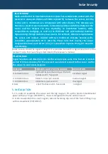
RECEIVER


SENSOR'S LIGHT EMITTING DIODE 


DESCRIPTION


3 indication bars 


lights almost permanently, with short 
breaks each 1.5 seconds 


excellent signal 


2 indication bars


blinks 5 times per second


medium signal 


1 indication bar


blinks twice per second


low signal


0 bars 

short fl ashes each 1.5 seconds  

no signal 


5. INSTALLATION  

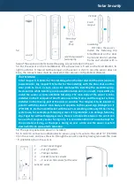
5.1 In order to assemble the sensor and the big magnet, lift up the plastic SmartBracket 

panel with your fi nger (PICTURE 1), move it alongside the frame and remove it.


In order to assemble the small magnet, take its fastening clip out of the frame lifting it up 

with a screwdriver (PICTURE 2).


Summary of Contents for DoorProtect Solar Plus

Page 1: ... magnet external contact battery CR123A installation set manual 4 SETTING UP PROCEDURES 4 1 Before installing the sensor it is required to register it with the Ajax security system In order to register the sensor it is necessary to switch the Ajax security system s receiver to Add Device mode the receiver s manual explains how to accomplish it and to put the switch 2 PICTURE 3 on the sensor to the...

Page 2: ...on considerably Make sure to check the signal strength It is possible to launch a signal level test on the receiver s side Test launching is described in the receiver s manual ATTENTION Signal level test and detection zone test for sensors take some time to start A certain period of time is necessary for the receiver to send a test request to the sensor and for the sensor to send a test response R...

Page 3: ... the sensor is to be installed on the fi xed part of door frame or window frame and the magnet is to be installed on the moving part of the door or window The magnet is to be located in parallel with the sensor s main body and opposite to the special sign triangle on it PICTURE 4 Fix the SmartBracket with the set s assembling units only Other fi xing system use for example self tapping screws of b...

Page 4: ...ppropriate signal to the alarm system receiver unit When the battery has run down with detection including the tamper triggering the sensor together with a usual indication turns on its light and turns it off placidly In order to replace the battery lift up the trigger 1 PICTURE 3 and remove the sensor s front cover Replace the battery PICTURE 5 with a new one type CR123A PICTURE 5 The sensor with...

Reviews: