6.
If the keypad is not the last device in the connection line, prepare a second
cable in advance. The ends of the wires of the rst and second cables,
which will be inserted into the keypad terminals, must be tinned and
soldered together, or crimped with special tips.
7.
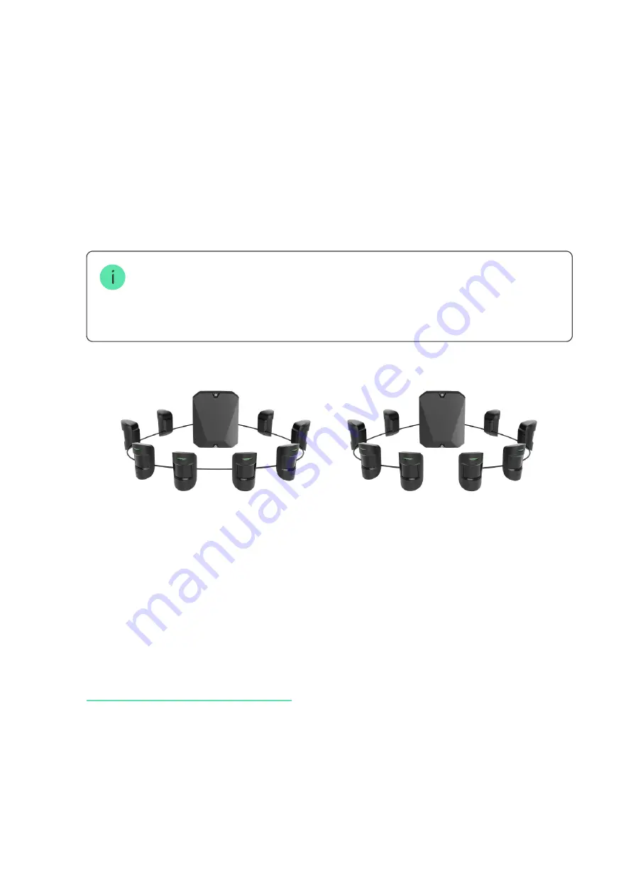
If the detector is the last in the line, install a termination resistor at the end
of the connecting line in case the
Star connection method
is in place. With
the
Ring connection method
, a termination resistor is not required.
More about connection methods (in progress)
We recommend connecting devices via the
Ring connection method
(hub – device
– hub), because, if the line is broken, the devices will be connected via the
Star
connection method
and will continue to transmit events to the hub. Noti cation
about the
Ring
failure will be sent to users and the security company.
8.
Temporarily secure the SmartBracket plate to a vertical surface using
double-sided tape or other temporary fasteners at the chosen installation
place. The recommended installation height is 1.3–1.5 meters above the
oor.
9.
Turn on the hub to supply the connected keypad with power. An LED of the
keypad will notify that the device is turned on.
10.
Add KeyPad Fibra to the system
11.
Conduct the Fibra signal strength test. The recommended signal strength
value is two or three bars. Otherwise, check the connection and the
condition of the wire.
12.
Attach the SmartBracket mounting panel with at least two xation points
using bundled screws. Use one of them on the perforated part of the mount
above the tamper. When using other fasteners, make sure they do not
damage or deform the mounting panel.


