6 .
adjustment method
Main power +B setting
Receive standard color pattern RF signal
,
set picture to
“
Standard Mode
”
. Adjust VR501
,
to get +B (VD631 -) voltage =110 V
7 .
I2C bus control adjustment methed:
enter and exit factory mode
7.1
1)
For remote controller of factory
continuous push [test] key on remote controller, the TV mode will change as follow:
Normal M BUS OPEN you can select “M” ( factory mode ) or “normal” mode.
2)
For remote controller of user
Push [menu] key,
→
display picture manual
→ push digital key 8500
→ display M.
Push [standby] key , exit factory mode and TV will be standby.
7.2
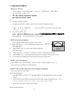
MENU8 Geometrical adjustment
.
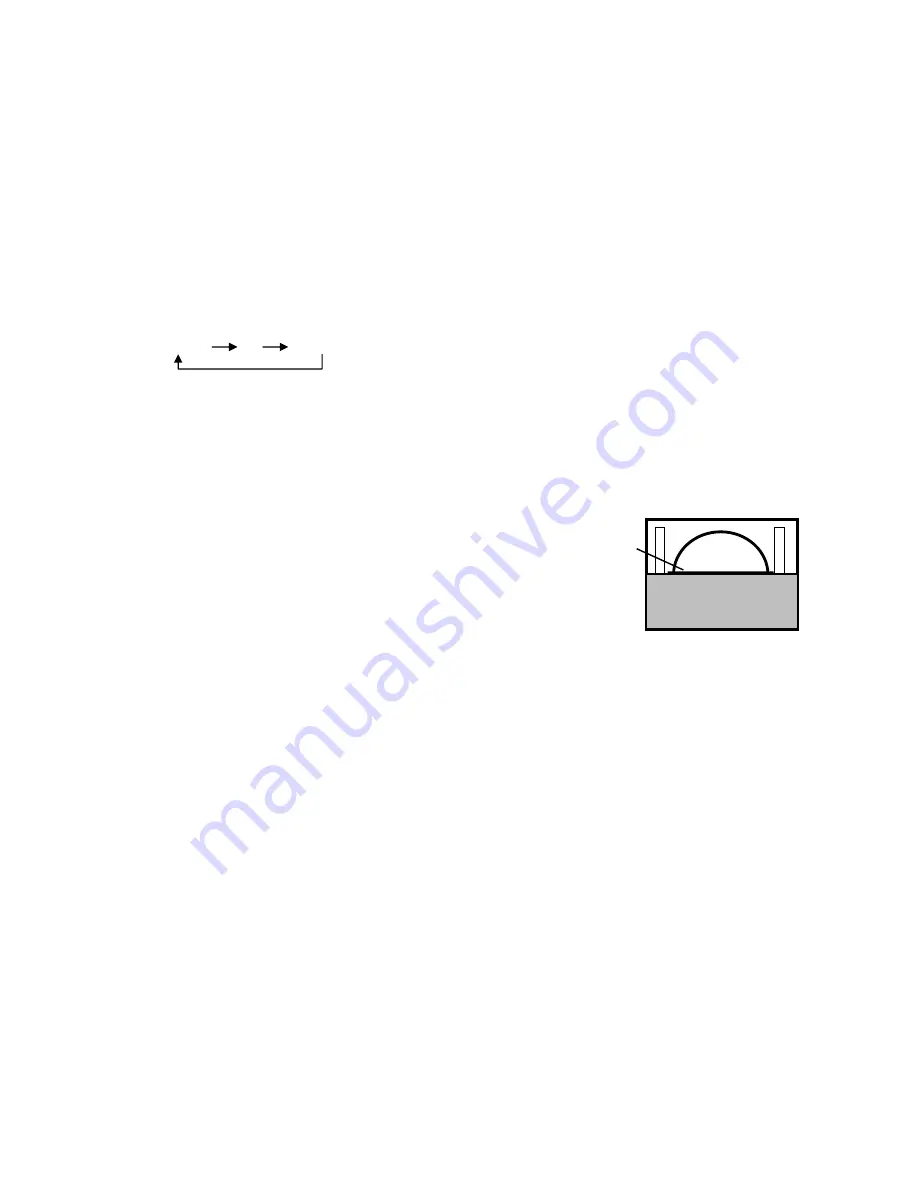
Receive standard Crosshatch pattern signal for PAL system .
Horizontal line
Shadow
1)
Adjust VSLOPE value
,
to the horizontal line just appear from
half bottom shadow.
2)
Adjust VSHIFT value
,
the center horizontal line correspond to
CRT vertical center.
3)
Adjust Vamp value
,
to get 90% of vertical picture contents would be displayed on CRT.
4)
Adjust HSHIFT value
,
to get the picture horizontal center correspond to CRT horizontal center.
5)
Receive standard Crosshatch pattern signal for NTSC system, and again adjust.
7.3
MENU7 AGC-TOP adjustment
Receive 60dBu (1mv)VH color bar signal
,
adjust AGC value
(
voltage from high to low
),
to
picture noise reduce gradually to be just disappeared.
7.4 MENU9 CRT cut-off and white balance and sub-brightness adjustment.
Reseive gray and white 2 steps signal.
a)
CRT cut off adjustment.
1.
push [
▲
P+][
▼
P-] key to select “SC”, push [
►
V+][
◄
V-] key then automatically vertical scan will be
stopped.
2.
adjust SCREEN control on Flyback transformer to get the darkest single horizontal line (red
、green、
or blue, sometimes shows more yellow、more purple or more white
).
3.
push [V+][V-] key again, vertical scan work repeat.
b)
white balance adjustment.
13
Summary of Contents for 21CTS92FS
Page 1: ...SERVICE MANUAL Model 21CTS92FS www akai ru COLOUR TV SET ...
Page 8: ...7 ...
Page 10: ...Fig 4 AN17821A illustration 9 ...
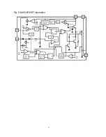
Page 11: ...Fig 5 KA5Q0765RT illustration 10 ...
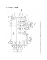
Page 12: ...11 Fig 6 TDA9859 illustration ...
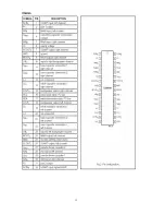
Page 13: ...12 ...
Page 19: ......


