4
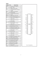
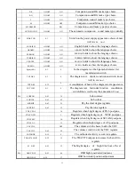
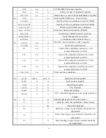
Pin39: +8V supply source.
Pin40: CVBS input
Pin42: Y signal input.
Pin43: C signal input.
Pin44: Main audio output
Pin45: RGB signal input blanking.
Pin46, Pin47, Pin48: RGB signal input.
Pin49: ABL. It means been current limiter input. The R464 is the control resister.
Pin50: Black current input from the CRT board.
Pin51, Pin52, Pin53: RGB drive signal output to the CRT board.
Pin54: +3.3V.
Pin55: GND.
Pin56: +3.3V.
Pin57, Pin58, Pin59: 12MHz crystal
。
Pin60: Reset, NC in this chassis.
Pin61: +3.3V
Pin62: This pin is connected to the HEF4052, Functions expanding.
Pin63: This pin is connected to the HEF4052, Functions expanding.
Pin64: IR signal input.
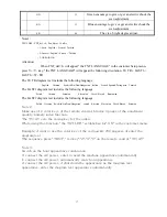
2 Memory AT24C08 is an E
2
PROM of 8k, pins describe as follows:
Pin1, Pin2, Pin3,Pin4, Pin7: GND. Pin8: +5V supply.
Pin5: SDA. Pin6: SCL.
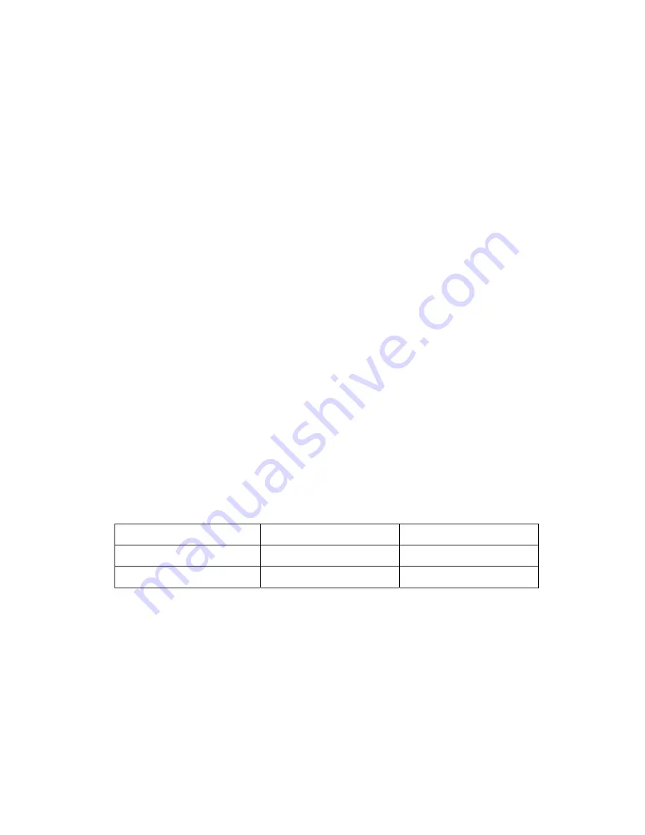
3 HEF4052 is described as follows:total 16 pins
HEF4052 Pin9
HEF4052 Pin10
STATE
0 0
TV
0 1
AV
Pin8: GND.
Pin16: +5V supply.
Summary of Contents for 21CTS92FS
Page 1: ...SERVICE MANUAL Model 21CTS92FS www akai ru COLOUR TV SET ...
Page 8: ...7 ...
Page 10: ...Fig 4 AN17821A illustration 9 ...
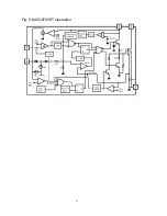
Page 11: ...Fig 5 KA5Q0765RT illustration 10 ...
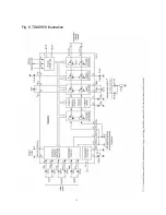
Page 12: ...11 Fig 6 TDA9859 illustration ...
Page 13: ...12 ...
Page 19: ......


