5
T
A
T
T
T
T
4. Signal process
he main chip is N301 TDA93X1 AV control switch HEF4052, sound driver is N101
N17821A
。
he TV signal inputs into the tuner (A101) from CABLE or antenna. The pin 10 and pin 11 of the
N301 are combined to select the band. The pin 4 of the N301 outputs the PWM tuning signal. The IF
video signal comes from the IF pin of the tuner. The 38.9MHz IF signal is coupled to the V308
(pre-amplify) and then to SAWF (Z301). After processed in the SAWF, the 38.9MHz signal gets to the
pin 23 and pin 24 of TDA93X1. The IF circuit in TDA93X1 includes such unit as the AGC amplifying
circuit, 38.9MHz oscillator, PLL video demodulator, video amplifier, IF identify circuit and AFT
circuit. The demodulated signal (CVBS) comes from the pin 38 of TDA93X1, the sound signal comes
from the pin 44.The internal CVBS signal needs norm identification then outputs from the pin 38 of
TDA93X1, via the trap-wave circuit (composed of the V351, Z354, Z352) feeds back to the pin 40 of
TDA93X1. The RGB signal comes from the pin51, Pin52, Pin53 of TDA93X1, and outputs to the
CRT board.
he internal sound signal comes from the pin 44 of TDA93X1, via the coupling capacitor C367
connects to the pin 3 and 5 of TDA9859. The TDA9859 is the audio effect processor, the AN7522N
is the driver. The TDA9859 includes bass, treble, balance, surround, effect shortcut options.
Through Synchronous separating circuit, the video signal is divided into
orizontal-Synchronizing signal and Vertical-Synchronizing signal. The horizontal-Sync pulse coming
from the pin 33 is ransferred to the horizontal-drive transistor, and will be used to drive the
horizontal-transformer. The horizontal-switch transistor is V451, it and the +B supply drives the
flyback transformer to generate the anode high voltage, the focus voltage, the screen voltage, the
CRT board drive voltage 180V, the vertical drive voltage 15V and -15V.
The vertical sawtooth wave is generated on the pin 21 and 22, and then enters the vertical output
amplifier circuit. The vertical output amplifier circuit is realized with the power amplifier IC
–LA78040.
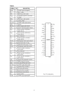
he TDA8177 is a 7 pins vertical deflection circuit (2 Amperes) for DC-coupled 90° or 110°
deflection systems with frame frequencies from 50 up to 120 Hz. Only a single supply voltage for the
scan and a second supply for the flyback are needed.
he vertical drive currents of N301 pins 21 and 22 are connected to input pins 1 and 7 of the
TDA8177. The currents are converted into a voltage by resistor R405. Pin 2 is on a fixed DC level
(internal bias voltage, about 2.3V) and on pin 1 the drive voltage can be measured (typical 1.4 Vpp).
Summary of Contents for 21CTS92FS
Page 1: ...SERVICE MANUAL Model 21CTS92FS www akai ru COLOUR TV SET ...
Page 8: ...7 ...
Page 10: ...Fig 4 AN17821A illustration 9 ...
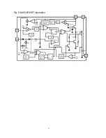
Page 11: ...Fig 5 KA5Q0765RT illustration 10 ...
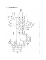
Page 12: ...11 Fig 6 TDA9859 illustration ...
Page 13: ...12 ...
Page 19: ......


