
29CTF05BS
3 – 24
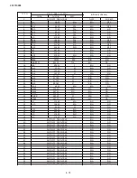
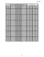
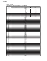
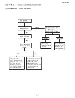
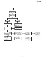
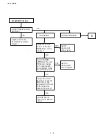
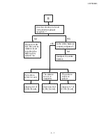
[2] ADJUSTMENT
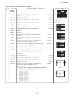
PIF ADJUSTMENT CHECKING
I
D
N
O
C
T
N
E
M
T
S
U
J
D
A
T
N
I
O
P
T
N
E
M
T
S
U
J
D
A
O
N
S
K
R
A
M
E
R
R
O
M
R
O
F
E
V
A
W
E
R
U
D
E
C
O
R
P
/
N
O
I
T
1
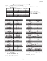
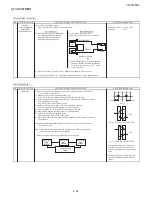
RF-AGC
(1) Receive "PAL COLOR BAR" signal.
C
D
V
4
.
0
±
6
.
3
:
e
g
a
tl
o
V
n
o
it
a
m
ri
f
n
o
C
)
n
o
it
a
n
i
m
r
e
t
m
h
o
5
7
(
V
µ
B
d
1
±
0
6
:
h
t
g
n
e
r
t
S
l
a
n
g
i
S
T
N
I
O
P
R
E
V
O
E
K
A
T
ADJUSTMENT
Monitor point
: TP53
(I2C BUS CONTROL)
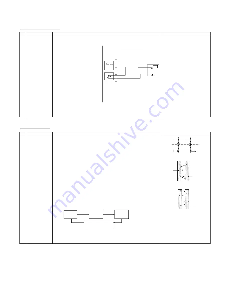
(2) Select "RF-AGC" item in the Adjustment
(2) Connect the oscilloscope to TP53.
Item. Push the RF-AGC button, blue
(Tuner's AGC Terminal) as shown in figure 3-1.
display with OK sign indicates the
adjustment is working properly.
(3) Select "RF-AGC" item in the Adjustment Mode.
Adjust the "RF-AGC" bus data to obtain the
Tuner output pin drop
0.1V ~ 1.0V
below
maximum voltage.
(4) Change the antenna input signal to 63 ~ 67dBµV, and make sure there is no noise.
(5) Turn up the input signal to 90 ~ 95 dBµB to be sure that there is no cross modulation beat.
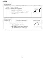
PURITY ADJUSTMENT
I
D
N
O
C
T
N
E
M
T
S
U
J
D
A
T
N
I
O
P
T
N
E
M
T
S
U
J
D
A
O
N
S
K
R
A
M
E
R
R
O
M
R
O
F
E
V
A
W
E
R
U
D
E
C
O
R
P
/
N
O
I
T
1
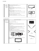
PURITY ADJ.
(1) Select the green monocolor screen with remote contoller, and set the beam current of
1.7mA with the contrast control.
(2) Degauss the CRT enough with the degausing coil.
Note: Follow the job instruction manual to adjust the magnetic field.
(3) The purity magnet must be previously set at the 0 magnetic field, and the convergence
must be adjusted to be rough.
With P-MAG, adjust it to the center - rank A.
Fig. 1-1
(4) Observe the points a,b, as shown in Fig.1-1 through the microscope.
Move DY fore and aft to set the landing at the point (Rank A).
(5) If the a/b balance is poor, compensate it to the center "Rank AB".
(6) Aline it to zero, keeping the raster rotation in the east direction.
(7) Tighten the deflection coil fastening screws.
Tightening torque : 108N ± 20N ( 11Kgf ± 2Kgf )
(8) Checking the CRT corner area, bond the magnetic sheet to set the landing at rank A for
compensation.
Fig 1 -2 . Rank A (On the right of CRT)
Note: Apply the adjustment after aging with the beam current 1700 ± 50µA or more for
30 minutes or more.
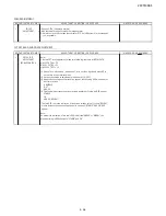
Note: Select the service mode, and press the monocolor key of R/C for process, and
the monocolor screen (green) will be selected.
* Every push of the monocolor key, changes the screen as follows.
Fig. 1 - 3 . Rank A (On the left of CRT)
*Continuously press the monocolor key
1 second or more, and the monocolor
mode will be selected without the service
mode.
*Even with TEXT key or "R/G/B" key, it can
be directly switched to each monocolor
screen.
Auto Adjustment
Manual Adjustment
Bias Box : about 4.5V
Fig. 3-1
OSCILLOSCOPE
BIAS BOX
TV SET
+
TP53
0.1V
~1.0V
+
-
-
Monocolor screen
release
mono color
GREEN
SCREEN
mono color
BLUE
SCREEN
mono color
RED
SCREEN
A
A=B
B
A
A=B
B
m
m
0
9
m
m
0
9
a
b
Summary of Contents for 29CTF05BS
Page 1: ...Service manual Colour TV set 29CTF05BS ...
Page 46: ...29CTF05BS 7 2 ...
Page 50: ...29CTF05BS 10 2 ...
Page 51: ...29CTF05BS 10 3 2 SCHEMATIC DIAGRAM CRT UNIT 29CTF05BS ...
Page 53: ...29CTF05BS 11 2 2 PWB A MAIN UNIT 1 MAIN UNIT COMPONENT SIDE ...
Page 54: ...29CTF05BS 11 3 ...
Page 55: ...29CTF05BS 11 4 2 MAIN UNIT CHIP PARTS SIDE ...
Page 56: ...29CTF05BS 11 5 ...