29CTF05BS
3 – 31
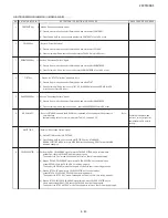
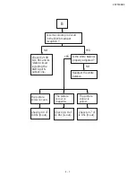
CHECKING FUNCTION OPERATION (2)
(VIDEO & AUDIO) CONTINUED
E
R
U
D
E
C
O
R
P
/
N
O
I
T
I
D
N
O
C
T
N
E
M
T
S
U
J
D
A
T
N
I
O
P
T
N
E
M
T
S
U
J
D
A
O
N
9
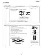
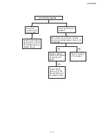
SOUND SYSTEM
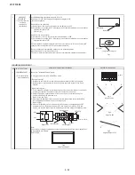
(1) Receive "PAL-D/K" signal, press the "SOUND SYSTEM" to select B/G, I.
Check the sound output is not working properly.
Select D/K and check the sound output to make sure it is working properly.
(2) Receive "PAL-I" signal, press the "SOUND SYSTEM" to select B/G, D/K.
Check the sound output is not working properly.
Select I and check the sound output to make sure it is working properly.
(3) Receive "PAL-B/G" signal, press
the "SOUND SYSTEM" to select I, D/K.
Check the sound output is not working properly.
Select B/G and check the sound output to make sure it is working properly.
10
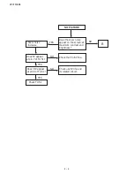
HEADPHONE
(1) Receive PAL COLOUR BAR with so
und 400Hz, 100% modulation (± 50kHz Dev).
OUTPUT CHECKING
(2) Maximum volume, and check the headphone output with 400kHz sound and no sound
out from speaker.
Ref : OUTPUT level of HEADPHONE is as following
Apx. 500mVp-p
11
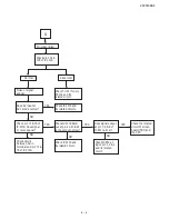
NOISE MUTE
(1) Receive "PAL COLOUR BAR" signal.
CHECKING
(2) Turn up the volume control to maximum, make sure the sound is heard from the speakers.
Then put the unit in no signal state.
(3) Check the sound mute is effective.
(4) Finally turn sound level of CTV to minimum.
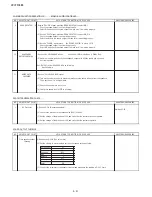
PROTECTOR OPERATION CHECK
E
R
U
D
E
C
O
R
P
/
N
O
I
T
I
D
N
O
C
T
N
E
M
T
S
U
J
D
A
T
N
I
O
P
T
N
E
M
T
S
U
J
D
A
O
N
1
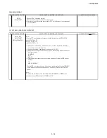
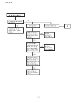
H.V Protector
(1) Receive E-5ch (Monoscopepattern).
Ref : Apx.13.3V.
(2) Connect the bias box to the cathode side (R607) of D604.
(3) Set the voltage of the bias box at 10V, and verify that the protector does not operate.
(4) Set the voltage of the bias box at 18V, and verify that the protector operate.
SOUND OUTPUT CHECKING
E
R
U
D
E
C
O
R
P
/
N
O
I
T
I
D
N
O
C
T
N
E
M
T
S
U
J
D
A
T
N
I
O
P
T
N
E
M
T
S
U
J
D
A
O
N
1
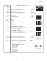
Front speaker output (1) Receive the E-10ch (PAL colour bar).
checking
(2) Set the volume to maximum and set the other sound setting as follow.
Setting item
Equalizer
Surround
BBE
Balance
AVL
Super Bass
Bass +
(3) Connect the voltmeter to the speaker terminal and make sure the reading is 5.0 ± 1 Vrms.
WAVEFORM OR REMARKS
WAVEFORM OR REMARKS
-
0
OFF
WAVEFORM OR REMARKS
ON
#1
Movie
OFF
-
Summary of Contents for 29CTF05BS
Page 1: ...Service manual Colour TV set 29CTF05BS ...
Page 46: ...29CTF05BS 7 2 ...
Page 50: ...29CTF05BS 10 2 ...
Page 51: ...29CTF05BS 10 3 2 SCHEMATIC DIAGRAM CRT UNIT 29CTF05BS ...
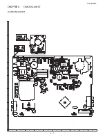
Page 53: ...29CTF05BS 11 2 2 PWB A MAIN UNIT 1 MAIN UNIT COMPONENT SIDE ...
Page 54: ...29CTF05BS 11 3 ...
Page 55: ...29CTF05BS 11 4 2 MAIN UNIT CHIP PARTS SIDE ...
Page 56: ...29CTF05BS 11 5 ...

