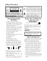
Safety Precaution
PRECAUTIONS DURING
SERVICING
1. In addition to safety, other parts and
assemblies are specified for conformance with
such regulations as those applying to spurious
radiation. These must also be replaced only
with specified replacements.
Examples: RF converters, tuner units, antenna
selection switches, RF cables, noise-blocking
capacitors, noise-blocking filters, etc.
2. Use specified internal Wiring. Note especially:
1) Wires covered with PVC tubing
2) Double insulated wires
3) High voltage leads
3. Use specified insulating materials for hazardous
live parts. Note especially:
1) Insulating Tape
2) PVC tubing
3) Spacers (insulating barriers)
4) Insulating sheets for transistors
5) Plastic screws for fixing micro switches
4. When replacing AC primary side components
(transformers, power cords, noise blocking
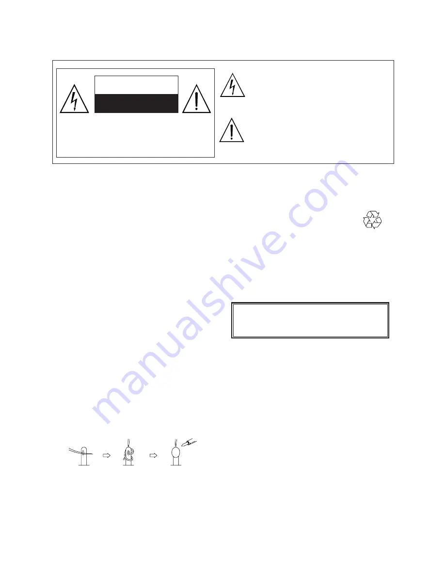
capacitors, etc.), wrap ends of wires securely
about the terminals before soldering.
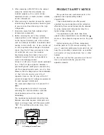
5. Make sure that wires do not contact heat
generating parts (heat sinks, oxide metal film
resistors, fusible resistors, etc.)
6. Check if replaced wires do not contact sharply
edged or pointed parts.
7. Make sure that foreign objects (screws, solder
droplets, etc.) do not remain inside the set.
The lightning flash with arrowhead symbol,
within an equilateral triangle, is intended to
alert the user to the presence of uninsulated
“dangerous voltage” within the product’s enclo
sure that may be of sufficient magnitude to
constitute a risk of electric shock to persons.
The exclamation point within an equilateral
triangle is intended to alert the user to the
presence of important operating and
maintenance (servicing) instructions in the
literature accompanying the appliance.
CAUTION: TO REDUCE THE RISK OF
ELECTRIC SHOCK, DO NOT REMOVE COVER
INSIDE. REFER SERVICING TO QUALIFIED
CAUTION
RISK OF ELECTRIC SHOCK
DO NOT OPEN
(OR BACK). NO USER-SERVICEABLE PARTS
SERVICE PERSONNEL ONLY.
MAKE YOUR CONTRIBUTION
TO PROTECT THE
ENVIRONMENT
Used batteries with the ISO symbol
for recycling as well as small accumulators
(rechargeable batteries), mini-batteries (cells) and
starter batteries should not be thrown into the
garbage can.
Please leave them at an appropriate depot.
WARNING:
Before servicing this TV receiver, read the
SAFETY INSTRUCTION and PRODUCT
SAFETY NOTICE.
SAFETY INSTRUCTION
The service should not be attempted by anyone
unfamiliar with the necessary instructions on this
apparatus. The following are the necessary
instructions to be observed before servicing.
1. An isolation transformer should be connected in
the power line between the receiver and the
AC line when a service is performed on the
primary of the converter transformer of the set.
2. Comply with all caution and safety related
provided on the back of the cabinet, inside the
cabinet, on the chassis or picture tube.
3. To avoid a shock hazard, always discharge the
picture tube's anode to the chassis ground
before removing the anode cap.
4. Completely discharge the high potential voltage
of the picture tube before handling. The picture
tube is a vacuum and if broken, the glass will
explode.
Summary of Contents for LCT-4216
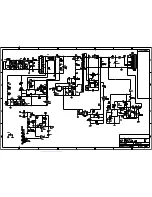
Page 15: ...CN A B VCC B 3 5VSB 5 AC VC B ON OFF AC AC AC VC CN B 5V 12V ...
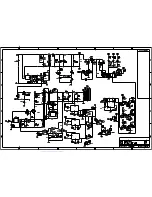
Page 17: ...DbhM4812V12_Vtek_BOM sch 1 Wed Oct 06 23 58 07 2004 ...
Page 18: ...DbhM4812V12_Vtek_BOM sch 2 Wed Oct 06 23 58 08 2004 ...
Page 19: ...DbhM4812V12_Vtek_BOM sch 3 Wed Oct 06 23 58 10 2004 ...
Page 20: ...DbhM4812V12_Vtek_BOM sch 4 Wed Oct 06 23 58 11 2004 ...
Page 21: ...DbhM4812V12_Vtek_BOM sch 5 Wed Oct 06 23 58 15 2004 ...
Page 22: ...DbhM4812V12_Vtek_BOM sch 6 Wed Oct 06 23 58 16 2004 ...
Page 23: ...DbhM4812V12_Vtek_BOM sch 7 Wed Oct 06 23 58 18 2004 ...
Page 24: ...DbhM4812V12_Vtek_BOM sch 8 Wed Oct 06 23 58 29 2004 ...
Page 25: ...DbhM4812V12_Vtek_BOM sch 9 Wed Oct 06 23 58 20 2004 ...
Page 26: ...DbhM4812V12_Vtek_BOM sch 10 Wed Oct 06 23 58 22 2004 ...
Page 27: ...DbhM4812V12_Vtek_BOM sch 11 Wed Oct 06 23 58 32 2004 ...
Page 28: ...DbhM4812V12_Vtek_BOM sch 12 Wed Oct 06 23 58 25 2004 ...
Page 29: ...DbhM4812V12_Vtek_BOM sch 13 Wed Oct 06 23 58 27 2004 ...
Page 30: ...Dbh1S4909V12 sch 1 Thu Oct 07 00 30 41 2004 ...
Page 31: ...Dbh1S4909V12 sch 2 Thu Oct 07 00 30 42 2004 ...
Page 32: ...Dbh1S4909V12 sch 3 Thu Oct 07 00 30 43 2004 ...
Page 33: ...Dbh1S4909V12 sch 4 Thu Oct 07 00 30 45 2004 ...
Page 34: ...Dbh1S4909V12 sch 5 Thu Oct 07 00 30 47 2004 ...
Page 35: ...Dbh1S4909V12 sch 6 Thu Oct 07 00 30 49 2004 ...
Page 36: ...Dbh1S4909V12 sch 7 Thu Oct 07 00 30 50 2004 ...
Page 37: ...DUBHE OSD Ver1 1_NAKS sch 1 Mon Oct 18 11 47 11 2004 ...
Page 38: ...0025 TTX sch 1 Thu May 05 23 47 54 2005 ...
Page 40: ......
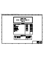
Page 63: ...MODEL NO PSM250 405 SPECIFICATION REVISION 01 DATE 2005 03 14 REV 01 PAGE 13 ...
Page 64: ...MODEL NO PSM250 405 SPECIFICATION REVISION 01 DATE 2005 03 14 REV 01 PAGE 14 ...
Page 77: ...Product Specification 2 LC420W02 Liquid Crystal Display Ver 1 1 August 12 2004 FRONT VIEW ...
Page 78: ...Product Specification 2 LC420W02 Liquid Crystal Display Ver 1 1 August 12 2004 REAR VIEW ...
Page 90: ......


