Pinout Information
Pin Descriptions
2.2.7
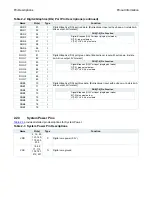
Digital Display Output Port Pins
Table 2-7
provides detailed pin descriptions for the Digital Display Output Port.
MRAS
225
O
SDRAM row address strobe. This signal is active low. [Tri-state output, 8mA drive,
5V-tolerant]
MCAS
226
O
SDRAM column address strobe. This signal is active low. [Tri-state output, 8mA drive,
5V-tolerant]
MWE
227
O
SDRAM write enable. This signal is active low. [Tri-state output, 8mA drive,
5V-tolerant]
MA0
213
O
SDRAM address bus. Multiplexed row and column address and bank select. Row
addresses use MA[11:0] for 8MB SDRAM and MA[10:0] for 2MB SDRAM. Column
addresses use MA[7:0]. [Tri-state output, 8mA drive, 5V-tolerant]
Note
: MA10 is a control signal during column address charging and pre-charging.
For 8MB SDRAM the bank select pins ba0 and ba1 should be connected to MA12 and
MA13, respectively. For 2MB SDRAM, connect ba0 to MA12.
MA1
210
O
MA2
207
O
MA3
204
O
MA4
203
O
MA5
206
O
MA6
209
O
MA7
211
O
MA8
214
O
MA9
217
O
MA10
215
O
MA11
220
O
MA12
221
O
MA13
218
O
MD0
255
I/O
SDRAM data bus. [Bi-directional, tri-state 8mA drive output, pull-up, 5V-tolerant]
MD1
252
I/O
MD2
248
I/O
MD3
245
I/O
MD4
242
I/O
MD5
239
I/O
MD6
236
I/O
MD7
232
I/O
MD8
231
I/O
MD9
234
I/O
MD10
238
I/O
MD11
241
I/O
MD12
244
I/O
MD13
247
I/O
MD14
250
I/O
MD15
254
I/O
Table 2-7 Digital Display Output Port Pin Descriptions
Name
Pin(s)
Type
Function
DVS
103
O
Digital display output port vertical sync. [Tri-state output, 4mA drive, 5V-tolerant]
DHS
104
O
Digital display output port horizontal sync. [Tri-state output, 4mA drive, 5V-tolerant]
DCLK
102
O
Digital display output port pixel clock. [Tri-state output, 8mA drive, 5V-tolerant]
Table 2-6 Memory Pin Descriptions (continued)
Name
Pin(s)
Type
Function
Summary of Contents for LCT2662
Page 25: ......
Page 26: ......
Page 27: ......
Page 28: ......
Page 29: ......
Page 30: ......
Page 31: ......
Page 32: ......
Page 33: ......
Page 34: ......
Page 94: ......
Page 95: ......
Page 96: ......
Page 97: ......
Page 98: ......
Page 99: ......
Page 100: ......
Page 101: ......
Page 102: ......
Page 103: ...Input configuration Power amplifier ...
Page 104: ......
Page 105: ......
Page 106: ......
Page 107: ......
Page 108: ......
Page 109: ......
Page 110: ......
Page 111: ...Exploded View Diagram Exploded View Diagram ...


