10
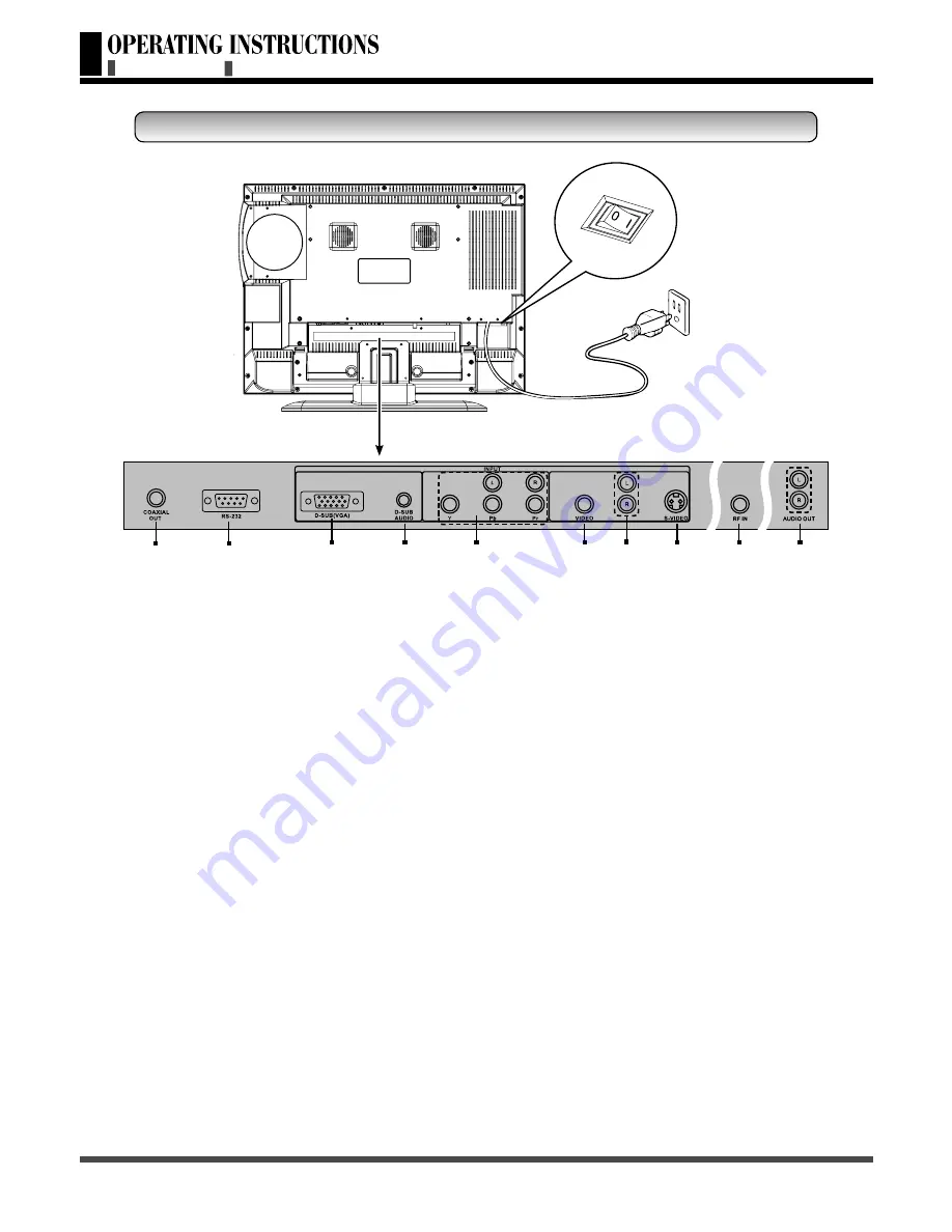
Sketch map
Push the power switch (O: Off, I: On).
Use the power cord connect to an earthed 120V, 60Hz AC outlet.
Signal input and other terminals:
. Coaxial Out: Connect to a digital audio component.
. RS-232: The D-SUB 9 pins terminal is used as a control port for serial communication between
PC and Panel. (For after sales service use only.)
. D-SUB(VGA) In: For PC display purpose. Connects to the Mini D-Sub 15 pins analog output
connector of the PC display card.
. D-SUB(VGA) Audio In: Connect the audio terminal to the audio output terminal of the PC.
. YPbPr In: Connect the separate component video cables to the device having component video
outputs (YPbPr) to the YPbPr terminal of the TV. YPbPr Audio In: Connect the audio cable to
device’s audio L and R terminal and to the L and R audio terminal of the TV.
. VIDEO In: Connect the video input terminal to the output terminal of the video output device.
. S-VIDEO In: Video input for external devices with an S-Video output, such as a camcorder or
VCR.
. AUDIO In: Connect the audio input terminal to the audio output terminal of the video output
equipment. With S-VIDEO audio input signals share this terminal.
. RF IN: Connect the antenna or cable set-top box with 75 Ohm F type connector into the RF IN
terminal.
. AUDIO Out: Audio outputs for external devices.
REMOTE CONTROL
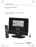
REAR VIEW
Rear View


