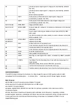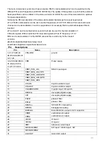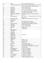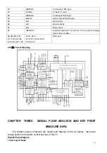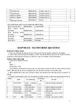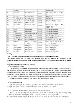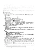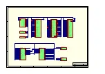
29
11
J171
Prepare to use
13
JP11
power supply plane
+12V
,
+12V
,
GND
,
GND
,
GND
,
GND
,
24V
,
24V
14
JP1
power supply plane
SB
,
GND
,
GND
,
5V
,
5V
,
5V
,
GND
,
GND
,
12V
,
12V
15
J700
Prepare to use
16
CN702
Prepare to use
17 CN700
remote
control
18 CN701
K
plane
19
CN304
Prepare to use
20
CN303
Prepare to use
21 JP701
display
22
CN306
Prepare to use
23
AVP303
DVI audio input
24 CN300
DVI
port
25 AVP300
VGAaudio
input
26 CN301
VGA
port
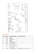
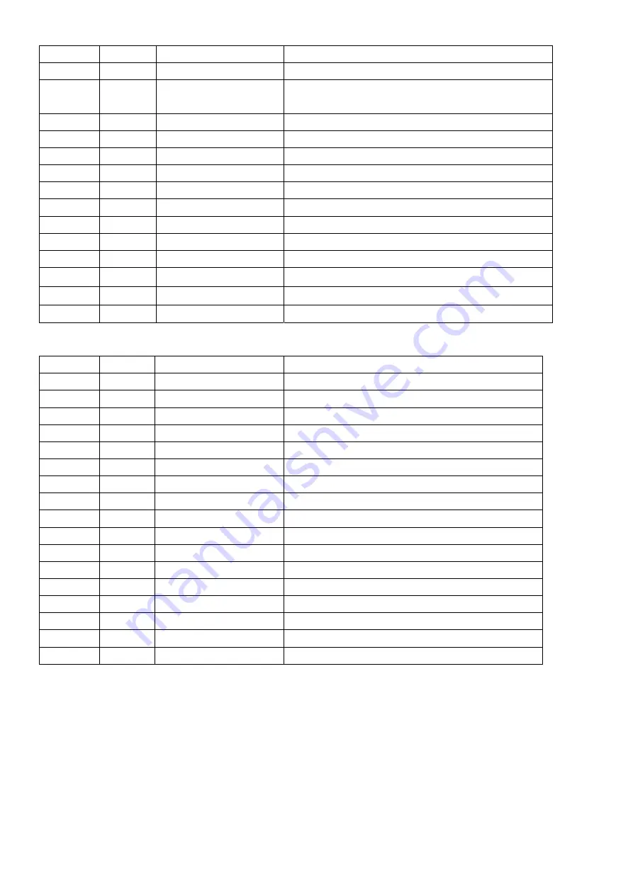
Main Components explanation:
Number Name Components
Function
Description
A U201
TDA15063H-N1B06557 Audio/video decoder
B U400
TDA8759HV/8/C1
Video signal AD converter
C U402
SAA7115HL/V1
Sub channel video decoder
D
U600
MT46V2M32LG-4
Frame buffer memorizer
E U700
GM1601/GM1501-BD Video
processor
F U305
SM5302AS-G-ET
HD signal filter
G U801
AM29LV800DT-70EC
Flash
,
the TV control procedure put in it
H U6
TPA3002D2PHPR Audio
PA
I U5
TDA9178T/N1
Video signal image improve
J K202
K9352N
Sound surface filter
K K201
K7262N
Sound surface filter
L UA3
FSAV330QSCX
Select switch
M U701
24LC32A T/SN
Buffer
N U307
FSAV330QSCX
Select switch
O U306
FSAV330QSCX
Select switch
P U302
24LC21A T/SN
EEPROM
Q U303
24LC21A T/SN
EEPROM
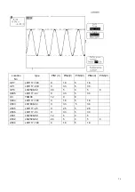
Main Point Wave Picture:
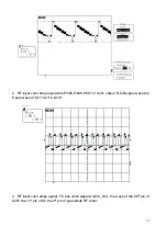
1 RF input color stripe signal, TV signal wave in the 19
P
th
P
pin of sub tuner UT1,The wave of
the 10
P
th
P
of SAA7115 also like this:

