CA810
1.1 Precautions
1.
Spill no liquids on the equipment and do not drop any objects through openings in
the equipment.
2.
Do not place the equipment near heat sources such as radiators, heating ducts, or amplifiers
and do not expose it to direct sunlight, excessive dust, moisture, rain, mechanical vibrations, or
shock.
2. Installation
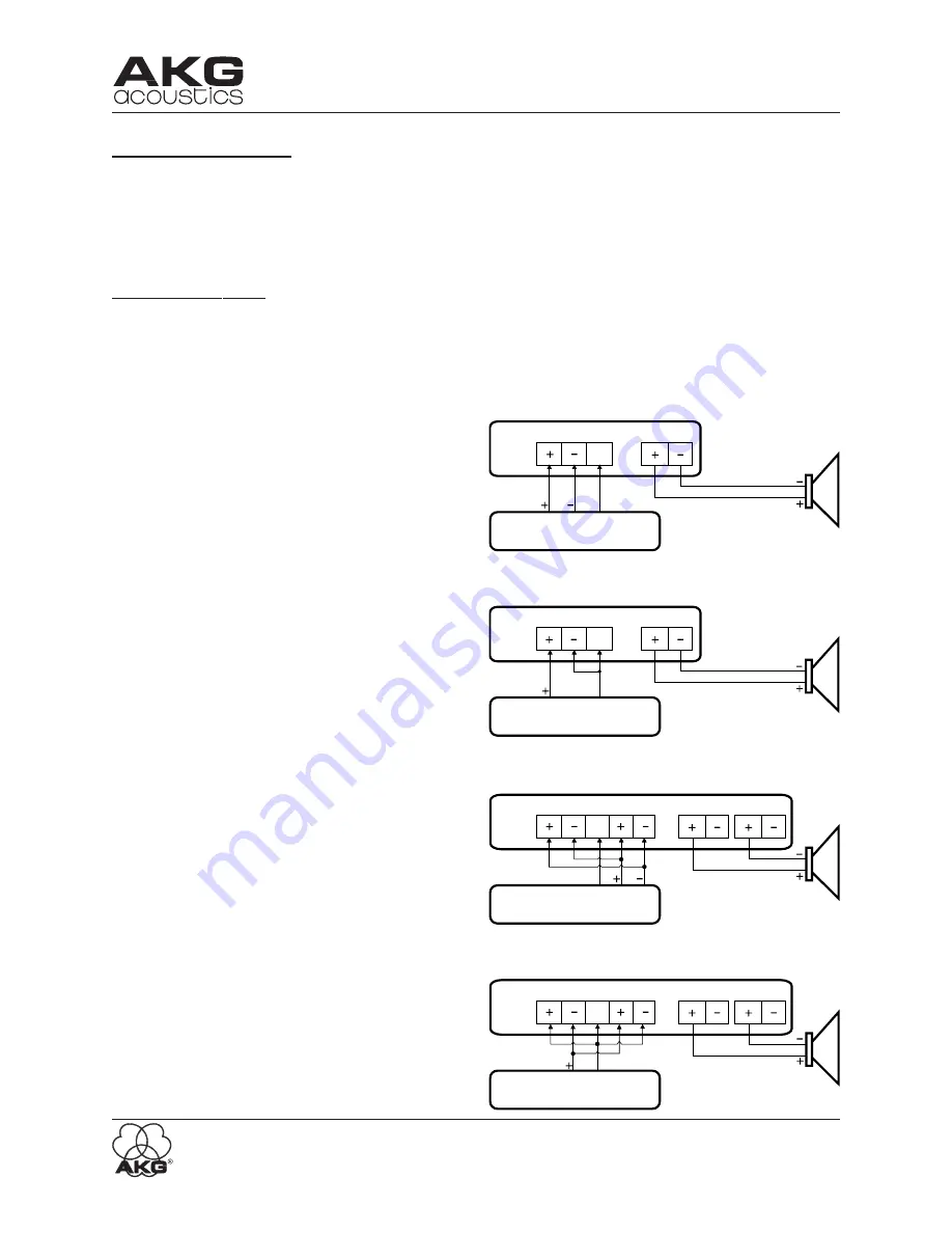
Installing the CA810 properly is simple, and only requires attention to a few issues. The CA810
should be used in a grounded metal rack. One open rack space should be provided above and
below the CA810 for proper ventilation. Shown below are the connections for both non-bridged
and bridged operation.
NON-BRIDGED OUTPUT
The standard CA810 configuration would have a
balanced output device (like the MM8 Matrix
Mixer) driving each channel of the CA810. The
speaker is connected in the non-bridged mode.
Maximum output power is 10W into 4 Ohms, or
6W into 8 Ohms. See Figure 2.
When driving the CA810 with an unbalanced
source, the (-) terminal is connected to the ground
of the driving signal, as well as the ground termi
nal of the CA810 input. Figure 3 shows this con
figuration.
Figure 3 - Unbalanced In / Non-Bridged Out
BRIDGED OUTPUT
Two adjacent channels of a CA810 may be con
nected as shown to allow bridging operation. In
the bridged mode, the minimum speaker load is
8 Ohms, and maximum power output is 20W into
8 Ohms. Note that since the Channel Level con
trols of both bridged channels will be active, they
should be set to the same level. The loudspeaker
is connected to the “+” output terminals of each
channel, while the “-” outputs are left uncon
nected. See Figure 4.
Figure 5 shows bridging operation using an un
balanced source.
Input
DRIVING DEVICE
CA
810
Input
Output
DRIVING DEVICE
GND
GND
GND
Output
GND
CA
810
Figure 2 - Balanced Input / Non-Bridged Output
In 1
Out 2
DRIVING DEVICE
Out 1
In 2
In 1
Out 2
DRIVING DEVICE
Out 1
In 2
GND
GND
GND
GND
CA
810
CA
810
Figure 4 - Balanced In / Bridged Out
Figure 5 - Unbalanced In /
Bridged Out
12


