Page 43 of 56
2.
This step is optional, but it is recommended if you listen for long periods at high
levels. Spread a thin film of thermal compound on the 3/8” wide ridge of the
heatsink (the side with two 6/32 mounting holes).
Note: the transformer is not yet fastened in place. Leave the chassis flat to avoid a
“gravitational accident” where the transformer goes rolling or sliding and leads rip
loose.
3.
Place the power supply module onto the chassis and secure it in place using two
black 6-32x3/8” pan-head Phillips screws inserted from the bottom of the chassis.
I like to do this by sliding the edge of the chassis over the edge of the table, and
inserting the screws from underneath the chassis.
4.
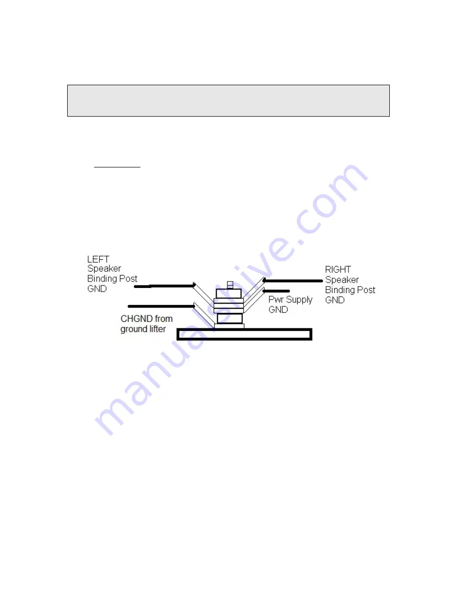
Ground Stud
a.
The ground stud already has a #6 lug, the black wire from the ground lifter
PCB, and a #6-32 nut holding the lug in place. Make sure the nut is tight.
b.
Above that nut, place these three #6 ground lugs:
i.
From the ground eyelet of the power supply PCB
ii.
From the ground (black) binding post of the left amplifier.
iii.
From the ground (black) binding post of the right amplifier.
c.
Place another #6-32 nut on top of the lugs, and tighten the nut to secure
the grounding lugs in place.
Figure 46-Grounding Stud Detail
Install the Wall and Fasten the Transformer Down
If you’ve been following along, the transformer is not yet fastened in place. This will
allow you to slide it toward the right chassis wall, making room to insert the divider-wall
into the chassis. You may even decide to temporarily stand the transformer on its side to
make extra room for this operation, but it really isn’t necessary. Check the front cover to
see which way the wall goes.
This is admittedly a bit of a Rubik’s cube operation, but if you slide the front end of the
wall right and the back end left, and get the wall under the front lip, it will fall into place.


