background image

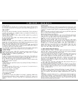
B - INTERNAL MENU

The Internal Menu of KURO allows us to parametrize many of its controls and also to MIDI 

4) MODE 4 - It will flash to the playing level around the ring.

map the device to act as a Controller.

5) MODE 5 - It will always on. You can adjust the setting brightness range 1 to 100.

Press button ENTER (SETUP MODE (19)) and KURO sets Internal Menu. Turn FOLDER 

6) MODE 6 - It will flash related to the setting speed. You can adjust the setting speed range 

(22) to scroll through the internal Menus as seen at the Display. Each Menu comprises some 

1 of fast flash to 100 of slow flash.

Submenus, turn control TRACK (20) to scroll through the internal Submenus.

7) MODE 7 - It will show the playing point similar to trail effect.

At the following draw there is an explanation for proper manipulation of Internal Menus 

8) MOCE 8 - It will light when the Jog Wheel is touched.

and Submenus. This explanation is valid for all manipulations with Internal Menus and 
Submenus shown later. We will use the JOG MODE Internal Menu as an example.

1- Press button ENTER (SETUP MODE (19)) to direct to Internal Menu of KURO. Turn 
the FOLDER knob until you can read at Display “JOG MODE”. 
2- Turn TRACK knob to select desired Mode.
3- Press and hold SHIFT (32) and turn TRACK (20) to adjust the second value (right side of 
Display) or parameter. Or simply turn the Jog Wheel (8) to select de desired value.1
4- Press button ENTER (SETUP MODE (19)) to exit the menu or press SAVE button to 
save your settings and exit the menu.

2. PLAYLIST 

Sets the Track search mode in case you have edited a database using the purpose build 
Software “Db Builder”. Search modes are Normal / Title/ Artist / Album/ Genre (only for 
USB storage).

More  info  at  D-  STEP  BY  STEP  FOR  IMPORTANT  OPERATION  1-  TRACK 
SEARCH page 26. 

3. SENSITIVITY   

Touch Wheel Sensitivity Adjustment (Adjustment range is -20~+20). 

4. PITCH BEND 


Internal Menus and Submenus 

Sets the range of Pitch of the PITCH BEND between the /-1%~100%.

1. JOG MODE

5. LINE SETUP 

Sets the LED ring of the Jog Wheel, gives us an idea about the Player position in the track. 

 Allow us to set the way the characters will appear at the Display. There are 3 possible modes 

At the Display we read “JOG Mode”. Below MODE Word we can two numbers that are the 

for each row. Four Submenus are available:

values of the parameters that determine the LED ring function on 1~8 a range. 

1- L1 mode = Modes 1~3 (sets first row)
2- L2 mode = Modes 1~3 (sets second row)

Setting the mode of the Jog Wheel LED ring:

3- Dis = 0.5~12.0 sec. (sets the time the characters remain still)
4- Run = 50~2000 msec. (sets the characters Speedy through the row)

1) MODE 1 - It will show the playing point indicator around the ring. You can adjust the 

Lines 1 / 2, Modes 1~3 description:

setting value range 1 of smallest indicator to 23 of full circle indicator.

- Mode1 = text goes through the row and stops (the stop time is parametrizable by user) 

2) MODE 2 - It will indicate the playing point opposite (on->of f / off<-on) when the Jog 

before staring the move through the row again. 

Wheel is touched. You can adjust the setting value range 1 of smallest indicator off to 23 of 

- Mode 2 = text goes through the row and stops.

full circle off.

- Mode 3 = text goes through the row continuously.

3) MODE 3 - It will show the playing point indicator around the ring and flash to the playing 
level  in  both  sides. You  can  adjust  the  setting  value  range  1  of  smallest  playing  point 
indicator to 23 of full circle indicator.

MODE 

1

  2

Playback Point

Playback Point

MODE 

1

  6

MODE 

2

  1

Playback Point

MODE 

3

  1

Playback Point

Light at music
rhythm

MODE 

7

  1

Playback Point

ENGLISH

23

MENU

Submenu

...................

...................

...

MENU

Submenu

Submenus

Value

...

...

Select Values

A)

or

 B)

+

Summary of Contents for KURO

Page 1: ...USER MANUAL MANUAL DE USUARIO CD USB PLAYER MIDI CONTROLLER KURO...

Page 2: ...ntactoconsu distribuidor 21 Durante cualquier manipulaci n del equipo para mantener todas las cualidades de ste tanto en 10 Protecci n del cable Escoja una posici n para el cable de corriente de modo...

Page 3: ...izables 500 4 por CD El valor de Pitch se indica en el Display 4botones de banco de memoria CUE LOOP programables M dulo Efectos parametrizables Ajustes de Pitch 6 10 16 or 100 DisplayVFD VacuumTube D...

Page 4: ...AKE es rotado hacia la posici n SLOWla reproducci n se para lentamente Control deArranque a Estando en modo VINYL 6 al girar la rueda presionando la parte central met lica en sentido inverso al de rep...

Page 5: ...adea crearun punto IN 2 Estando en modo PAUSAy estando el bot n CUE iluminado al tocar la parte met lica Modo VYNIL para conseguir la reproducci n por frames deberemos girar la rueda superior de la ru...

Page 6: ...AUSE si presionamos el bot n NEXT Ver m s informaci n D EXPLICACI N PASO A PASO DE LAS DISTINTAS TRACK parpadea utilizando los controles FORDER y TRACK seleccionamos una OPERACIONES 4 RECUPERAR PUNTOS...

Page 7: ...CUE sin pausar la reproducci n Este tipo de punto Cue se suele llamar hot cue o Cue on the fly Adem s simult neamente determina el punto de inicio deunLoop 27 EFECTOS Su equipo dispone de tres efectos...

Page 8: ...OUS En este modo la reproducci n de las pistas en continua INDICADOR RELOOP En el Display aparecer la palabra RELOOP cuando tengamos un Loop creado pero no en reproducci n Al reproducir el Loop el ico...

Page 9: ...velocidad de reproducci n Podremos Verm s informaci n E CONTROLADOR MIDI p gina 15 ajustar la intermitencia del parpadeo en un rango de 1 r pido a100 lento A MIDI SETUP 7 Modo 7 el anillo mostrar la r...

Page 10: ...r editar la iluminaci n de los LED de su Normal Title Artist Album Genre delmen PLAYLIST equipo mediante par metros MIDI an logamente a como hemos visto en el apartado B MIDINOTEEDIT Ver el MapadeAsig...

Page 11: ...equipo Processing Base de Datos aparecer un informe del an lisis Esto indica que la creaci n de la Base de Datos ya ha sido creada NOTA cada vez que modifique el contenido de su dispositivo USB es ne...

Page 12: ...n el Display la informaci n del Nombre de ARTISTA y la pista de dicho Artista que comienza con la primera letra seg n el orden del abecedario Girando el control TRACK nos desplazaremos por las pistas...

Page 13: ...enarinternamente2000puntos CUE bot n la reproducci n entraen modo PAUSAen elpunto CUE del bot n BANK presionado 4 puntosporCD esdecir500CDs El ltimobot nBANK presionado parpadear 4 puntosCUEporcarpeta...

Page 14: ...metro Time en Beats o fracciones de Beat utilizando la funci n FX BEAT SYNC EFECTOFILTER ste bot n activa desactiva el efecto Filtro Este efecto cambia la tonalidad de la m sica en funci n del tipo de...

Page 15: ...ot n HOLD no est activo cualquier modificaci n del par metro ser moment nea 2 GireelcontrolFORLDER 22 hastaqueaparezcaelSubmen MIDISETUP 2 Si el bot n HOLD est activo cualquier modificaci n del par me...

Page 16: ...adecimal 10h es el n mero siguiente aFh a CC ABSOLUTE VR CC Control Change Absoluto VR potenci metro Decimal 0 1 2 3 4 5 6 7 8 9 10 1112 13 14 15 16 17 etc Los mensajes Control Change Absoluto se env...

Page 17: ...al utilizando la La direcci n MIDI del control Folder SW es 2B en base Hexadecimal Convertimos de tabladeconversi nHexa Dec hexadecimal adecimal utilizando la tabla de conversi n Hexa Dec Columna 7 Fi...

Page 18: ...ry power or shoulduseamountingaccessoryrecommendedbythemanufacturer other sources referthe operating instructions 21 Lightning For added protection for this product during a lightning storm or when it...

Page 19: ...rse _2000 programmable Cue Points 500 track x4 for CD _Pitch display _4Programmable Cue Bank Buttons _RCAcoaxial output _Adjustable Pitch Percentages 6 10 16 or 100 _Large brightVFD display _ Instant...

Page 20: ...ull playback speed is reached when the jog dial is backspin b When in the CDJ mode this START dial determines the acceleration speed until full playback speed is reached when the PLAY PAUSE button is...

Page 21: ...p b To store your loops and cue points that are saved in the BANKS to the system memory fornexttime presstheMEMORYbuttonfor1second NOTE RECALL MEMORY KURO can store 2000 programmed cue points in 500 t...

Page 22: ...TONS Note Please DO NOTtouch the sensitive JOGWheel underA Cue Scratch mode This search button allows you to quickly scan backwards through atrack 25 OUTBUTTON This search button allows you to quickly...

Page 23: ...T Use this jack to connect to a computer or link a host USB player 37 USB 2 PORT This is the USB port where you insert your USB mass storage device 38 38 37 36 35 34 33 40 39 53 47 BPM METER This mete...

Page 24: ...TION 1 TRACK SEARCH page 26 3 SENSITIVITY TouchWheel SensitivityAdjustment Adjustment range is 20 20 4 PITCH BEND Internal Menus and Submenus Sets the range of Pitch of the PITCH BEND between the valu...

Page 25: ...set this function as HOLD orTOGGLE DSP VerXX DSPversion JOG OUTPUT 0 30 ms Control JOG MIDI max send time We can set the delay response of the Jog Wheel The setting range is 0 a 30 miliseconds G LOAD...

Page 26: ...ER knob and you change the contents of yourUSB device turn JogWheel to select next Artist PLAYLIST c Each press TRACK knob you can select the ID3 of track 1 Press the ENTER SETUP MODE button to enter...

Page 27: ...the second row Turn controlTRACK 20 and scroll through all theTracks of the selectedArtist In Playlist Album mode At internal menu we set Album as search mode Search process will be Press and turn FOL...

Page 28: ...k button Playback will Start from the CUE point stored and will keep 4CUE points each 500 tracks for CD ON meanwhile we keep the Bank button pressed If we release the button Playback stops at 4CUE poi...

Page 29: ...effects parametrizable in time and ratio are avaialble Time Parameter will determine Time parameter can be set using the JogWheel or setting it in Beat values using the function the change in sound an...

Page 30: ...seconds We enter MIDI mode the three LEDs light Use the buttons placed at the sides of the LEDs row to select the Beat Syncrony of up In MIDI mode Kuro becomes a MIDI Controller tied to a DJ Software...

Page 31: ...ol Change messages are sent with status 0x9n SWITCH On and Off value are 0x7F and 0x00 where n is the channel d LED ON OFF LED These messages are used for LED Control Change messages are sent with sta...

Page 32: ...O SW LED 2F 2F B 2 CC47 6E 2F D8 CC47 ECHO SW LED 05 05 F 1 CC5 44 05 G 4 CC5 FLANG SW LED 29 29 F 2 CC41 68 29 G 7 CC41 FILTER SW LED 23 23 B1 CC35 62 23 D7 CC35 LOOP SW LED 30 30 C 3 CC48 6F 30 D 8...

Page 33: ...E2 SHIFT SW G7 SW G 1 SHIFT SW A 4 SW D 1 SHIFT SW F 4 SW A 1 SHIFT SW C5 ENC Cc53 SHIFT ENC Cc116 SW A 5 JOG CC TYPE RELATIVE SW G0 ENC Cc53 SHIFT ENC Cc116 JOG CC TYPE NOTE CW ENC Cc54 SHIFT ENC Cc...

Page 34: ...SALIDA WITHIN 0 2dB WITHIN 1dB 1KHz 0dB 2 CHANNEL BALANCE CD 0 01 1KHz 0dB USB 1 2 0 01 1KHz 0dB 6 THD N 1 90dB 1KHz 0dB 7 S N RATIO 2 RATIO SE AL RUIDO RESPUESTA EN FRECUENCIA NIVEL MAX AURICULARES C...

Page 35: ...Kbps MP3 Format MPEG 2 5 Layer 3 standard which provides for similar coding at sampling rates of 8 11 025 and 12 kHz 32 40 48 56 64 80 96 112 144 160 Kbps Disc at Once and Track at Once Disc Writing M...

Page 36: ...C Praga n 11 Pol Ind Cova Solera 08191 Rub Barcelona SPAIN www akiyamadj com info akiyamadj com...

Reviews: